CH32V307教程 [第四集] [通信协议]
目录
完成CH32V307某一外设程序流程总结
根据上两篇教程的经验,我们可以发现规律,并整理出一套流程,用于以后针对某一目标的嵌入式程序解决方案。
第一步,我们需要明确自己程序的目标,分析此程序需要用到哪些外设,然后查看开发板的文档或者原理图,得知这些外设使用的是哪些引脚,再阅读芯片的应用手册与数据手册来了解芯片的这些外设的有无和其他芯片不同的地方。
第二步,参考沁恒官方提供的EVT例程逐个将需要用到的外设调试好。
第三步,整合已经调整好的例程去完成目标程序,编写main函数与各个中断服务函数。
UART 轮询收发
任务目标
UART 收发例程(轮询):使用 USART2 收发数据
基础知识
CH32V307 拥有的并不是普通的 UART 而是 USART。
USART:通用同步和异步收发器
UART:通用异步收发器
UART 与 USART 进行异步通信时,这两者是没有区别的,区别在于 USART 比 UART 多了同步通信功能,这个同步通信功能可以把 USART 当做 SPI 来用,比如用 USART 来驱动 SPI 设备。
实现过程
新建工程,修改晶振启动超时阈值 HSE_STARTUP_TIMEOUT = 4000
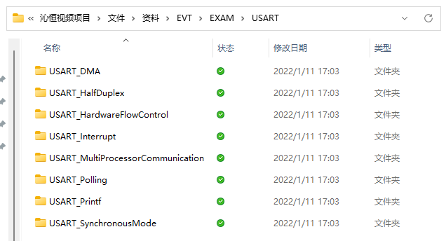
此次用于参考的沁恒官方例程有两份,第一份是创建工程时提供的 debug.c, 第二份是在官方例程 EVT -> USART下的项目。

由于懒的打开其他工程的原因这里选择 debug.c 作为我们的参考例程。
3.在 debug.c 中有关于 USART 的代码有两段。
第一段
   /*******************************************************************************
   * Function Name  : USART_Printf_Init
   * Description    : Initializes the USARTx peripheral.
   * Input          : baudrate: USART communication baud rate.
   * Return         : None
   *******************************************************************************/
   void USART_Printf_Init(uint32_t baudrate)
   {
     GPIO_InitTypeDef GPIO_InitStructure;
     USART_InitTypeDef USART_InitStructure;

   #if (DEBUG == DEBUG_UART1)
     RCC_APB2PeriphClockCmd(RCC_APB2Periph_USART1| RCC_APB2Periph_GPIOA, ENABLE);

     GPIO_InitStructure.GPIO_Pin = GPIO_Pin_9;
     GPIO_InitStructure.GPIO_Speed = GPIO_Speed_50MHz;
     GPIO_InitStructure.GPIO_Mode = GPIO_Mode_AF_PP;
     GPIO_Init(GPIOA, &GPIO_InitStructure);

   #elif (DEBUG == DEBUG_UART2)
     RCC_APB1PeriphClockCmd(RCC_APB1Periph_USART2, ENABLE);
     RCC_APB2PeriphClockCmd(RCC_APB2Periph_GPIOA, ENABLE);

     GPIO_InitStructure.GPIO_Pin = GPIO_Pin_2;
     GPIO_InitStructure.GPIO_Speed = GPIO_Speed_50MHz;
     GPIO_InitStructure.GPIO_Mode = GPIO_Mode_AF_PP;
     GPIO_Init(GPIOA, &GPIO_InitStructure);

   #elif (DEBUG == DEBUG_UART3)
     RCC_APB1PeriphClockCmd(RCC_APB1Periph_USART3, ENABLE);
     RCC_APB2PeriphClockCmd(RCC_APB2Periph_GPIOB, ENABLE);

     GPIO_InitStructure.GPIO_Pin = GPIO_Pin_10;
     GPIO_InitStructure.GPIO_Speed = GPIO_Speed_50MHz;
     GPIO_InitStructure.GPIO_Mode = GPIO_Mode_AF_PP;
     GPIO_Init(GPIOB, &GPIO_InitStructure);

   #endif

     USART_InitStructure.USART_BaudRate = baudrate;
     USART_InitStructure.USART_WordLength = USART_WordLength_8b;
     USART_InitStructure.USART_StopBits = USART_StopBits_1;
     USART_InitStructure.USART_Parity = USART_Parity_No;
     USART_InitStructure.USART_HardwareFlowControl =  USART_HardwareFlowControl_None;
     USART_InitStructure.USART_Mode = USART_Mode_Tx;

   #if (DEBUG == DEBUG_UART1)
     USART_Init(USART1, &USART_InitStructure);
     USART_Cmd(USART1, ENABLE);

   #elif (DEBUG == DEBUG_UART2)
     USART_Init(USART2, &USART_InitStructure);
     USART_Cmd(USART2, ENABLE);

   #elif (DEBUG == DEBUG_UART3)
     USART_Init(USART3, &USART_InitStructure);
     USART_Cmd(USART3, ENABLE);

   #endif
   }
这段代码涵盖了初始化 USART1,USART2,USART3 的初始化代码,我们只需要保留 USART2 的初始化代码即可,如下:
   /********************************************************************
   * 函 数 名       : USART2_Init
   * 函数功能    : 初始化 usart2
   * 输    入          : 无
   * 输    出          : 无
   ********************************************************************/
   void USART2_Init(void)
   {
      GPIO_InitTypeDef  GPIO_InitStructure;
      USART_InitTypeDef USART_InitStructure;
      //开启时钟
      RCC_APB1PeriphClockCmd(RCC_APB1Periph_USART2, ENABLE);
      RCC_APB2PeriphClockCmd(RCC_APB2Periph_GPIOA, ENABLE);

      /* USART2 TX-->PA2  RX-->PA3 */
      GPIO_InitStructure.GPIO_Pin = GPIO_Pin_2;
      GPIO_InitStructure.GPIO_Speed = GPIO_Speed_50MHz;
      GPIO_InitStructure.GPIO_Mode = GPIO_Mode_AF_PP;
      GPIO_Init(GPIOA, &GPIO_InitStructure);
      GPIO_InitStructure.GPIO_Pin = GPIO_Pin_3;
      GPIO_InitStructure.GPIO_Mode = GPIO_Mode_IPU;                 //RX,输入上拉
      GPIO_Init(GPIOA, &GPIO_InitStructure);

      USART_InitStructure.USART_BaudRate = 115200;                    // 波特率
      USART_InitStructure.USART_WordLength = USART_WordLength_8b;    // 数据位 8
      USART_InitStructure.USART_StopBits = USART_StopBits_1;          // 停止位 1
      USART_InitStructure.USART_Parity = USART_Parity_No;           // 无校验
      USART_InitStructure.USART_HardwareFlowControl = USART_HardwareFlowControl_None; // 无硬件流控
      USART_InitStructure.USART_Mode = USART_Mode_Tx | USART_Mode_Rx; //使能 RX 和 TX

      USART_Init(USART2, &USART_InitStructure);

      USART_Cmd(USART2, ENABLE);                                     //开启UART
   }
这样 USART2 的初始化代码即可完成。
debug.c 中有关于 USART 的第二段代码
   /*******************************************************************************
   * Function Name  : _write
   * Description    : Support Printf Function
   * Input          : *buf: UART send Data.
   *                  size: Data length
   * Return         : size: Data length
   *******************************************************************************/
   int _write(int fd, char *buf, int size)
   {
     int i;

     for(i=0; i<size; i++)
     {
   #if (DEBUG == DEBUG_UART1)
       while (USART_GetFlagStatus(USART1, USART_FLAG_TC) == RESET);
       USART_SendData(USART1, *buf++);
   #elif (DEBUG == DEBUG_UART2)
       while (USART_GetFlagStatus(USART2, USART_FLAG_TC) == RESET);
       USART_SendData(USART2, *buf++);
   #elif (DEBUG == DEBUG_UART3)
       while (USART_GetFlagStatus(USART3, USART_FLAG_TC) == RESET);
       USART_SendData(USART3, *buf++);
   #endif
     }

     return size;
   }
有用的代码只有一句
USART_SendData(USART2, *buf++);
含义是通过 USART2 发送字符串。
由于我们的任务目标是数据回环所以我们需要接受数据的函数。
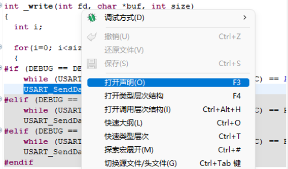
右击 USART_SendData() 打开声明去沁恒UART 官方库中找一下接受数据的函数。

下一个函数就是 USART_ReceiveData()
	/*******************************************************************************
	* Function Name  : USART_ReceiveData
	* Description    : Returns the most recent received data by the USARTx peripheral.
	* Input          : USARTx: where x can be 1, 2, 3 to select the USART peripheral.
	* Return         : The received data.
	*******************************************************************************/
	uint16_t USART_ReceiveData(USART_TypeDef* USARTx)
	{
	  return (uint16_t)(USARTx->DATAR & (uint16_t)0x01FF);
	}
结合这两个函数完成数据回环的main函数。
	/********************************************************************
	* 函 数 名       : main
	* 函数功能    : 主函数
	* 输    入          : 无
	* 输    出          : 无
	********************************************************************/
	int main(void)
	{
	    USART2_Init();           /* USART INIT */
	    int i = 0;
	    char str[]="Loop back from USART2.\r\n";     //发送一条提示语
	    while(str[i]){
	        while(USART_GetFlagStatus(USART2, USART_FLAG_TXE) == RESET);    //等待 上次发送 结束
	        USART_SendData(USART2, str[i]);                                 //发送数据
	        i++;
	    }
	    Delay_Ms(500);
	    int recv;
	    while(1){
	        //串口回环,把接收到的数据原样发出
	        while(USART_GetFlagStatus(USART2, USART_FLAG_RXNE) == RESET);   //等待接收数据
	        recv = USART_ReceiveData(USART2);                               //读取接收到的数据
	        while(USART_GetFlagStatus(USART2, USART_FLAG_TXE) == RESET);    //等待上次发送 结束
	        USART_SendData(USART2, recv);                                   //发送数据
	    }
	}
实验现象
- 进入PuTTY官方下载网站下载 PuTTY 串行接口连接软件,下载完成后直接双击打开,点击
Serial 后设置开发板所连接端口(成功连接开发板后可打开设备管理器得知)与波特率 115200,最后点击 open 打开串口终端。
- 随意发送字符串,开发板将会将发送过去的字符串返回。
 网站备案号:ICP备16046599号-1