Design of digital multimeter
Introduction of ADC (Analogue-to-digital convector)
The main difference between digital multimeter and conventional multimeter is how to show the magnitude of the quantity measured. For conventional multimeter, we have discussed that it uses coil in a magnetic field and depends on the deflection of needle to show the magnitude. For digital multimeter, we do not use coil instead we use a new component called ADC (Analogue-to-digital convector). Before we start designing the multimeter we need to briefly introduce how ADC works. As its name suggests, it is a component that can convert analogue data (continuous data) into digital data (discrete data). There is another component which has the opposite effect of ADC, which is called DAC (Digital-to-analogue convector). DAC is not used in this project so I do not introduce it. if you are interested about it, you can go to (https://en.wikipedia.org/wiki/Digital-to-analog_converter) for more information. Do back to ADC. There are many kinds of different ADC, including Successive Approximation ADC (https://en.wikipedia.org/wiki/Successive-approximation_ADC ), Integral ADC (https://en.wikipedia.org/wiki/Integrating_ADC ), flash ADC (https://en.wikipedia.org/wiki/Flash_ADC ), Voltage frequency conversion ADC (https://www.asdlib.org/onlineArticles/elabware/Scheeline_ADC/ADC_visual/voltage1.html ), ∑- Δ Type ADC (https://en.wikipedia.org/wiki/Delta-sigma_modulation ) and Pipeline ADC (https://www.maximintegrated.com/en/design/technical-documents/tutorials/1/1023.html ).
Here I would discuss about two kinds, one is flash ADC (Figure 43)and one is Successive Approximation ADC (Figure 44).
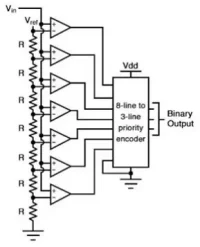 Figure43
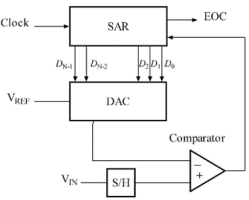 Figure44
For flash ADC, there is a reference voltage which is the maximum voltage that it can measure. There are several resistors connected in series to divide reference voltage. Then, measured voltage is introduced and operation-amplifier will compare the magnitude of the measured voltage and part of the reference voltage and check which level the measured voltage reach. Then, encoder will output the magnitude of the voltage in digital form.
For Successive Approximation ADC, there is only one operation-amplifier. First, half of reference voltage is compared with measured voltage. If measures voltage is larger than it, compare measured voltage with ¾ reference voltage, otherwise compare it with ¼ reference voltage. Then, repeat doing. The smallest division is 1/2n *VR (VR is reference voltage). Depending on this, encoder can output the magnitude of the voltage in digital form.
Both of them have advantages and disadvantages, for flash ADC, it is fast and it is easy to understand. For Successive Approximation ADC, its internal structure is complex and its processing speed is slower but it uses less electronic components (it only uses one operation-amplifier).
I also draw a flash ADC (Figure 45). There are 8 operation-amplifiers so the digital output consists of 3 digits. If you want more precise data, you can connect more flash ADC together (Figure 46). But take care as the number of digit increases, the number of flash ADC you need would increase exponentially. For example, to get a four-digit ADC, you need two three-digit ADC. However, to get a five-digit ADC, you need four three-digit ADC.
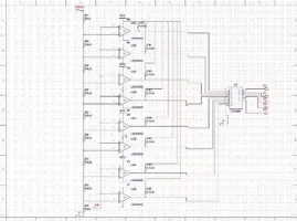 Figure45
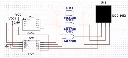 Figure46
A general introduction of what I want to do
ADC is a complex component so it is hard for me to use a self-designed ADC. In this stage, I would use ADC in Arduino, which has its own Successive Approximation ADC. In addition, using Arduino has many other advantages and I would mention them in my later introduction. For conventional multimeter, coil has the same function as ADC, namely convert the magnitude of the quantity into another form that we can understand. For conventional multimeter, there is a needle to show the result so in digital multimeter, we also need a component to show our result. Here, I would use a screen called ST7789 to demonstrate my result. Still, for digital multimeter I need to set several gears so some resistors are needed.
Design of voltage principle circuit
Before we draw the circuit, we need to think about a question, namely can we just connect ADC to measure voltage like Figure 47.
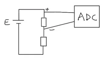 Figure47
Obviously, the answer is not. There are two reasons. First, ADC is also a very complex component, if we just connect it into the measured circuit, it would affect the voltage of the measured circuit. In addition, there are a maximum voltage that ADC can hold. For the ADC in Arduino, which we would use, the maximum voltage is 5V so the range of voltage that we can measure is very limited. Let us solve this question one by one. For the first problem, I would like to introduce a new electronic component called operational-amplifier (https://en.wikipedia.org/wiki/Operational_amplifier ). This is a useful component and its function includes Comparing two voltage, Amplifying voltage and Separating two circuits (the functions depend on how you connect the operation-amplifier) . For this project, I would use the last two functions. For the first function, we have mentioned it in ADC. Then, we need to increase the range of voltage that we can change. With the consideration of the two factors, we draw a circuit like Figure 48.
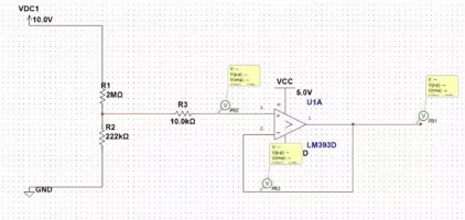 Figure48
To increase the range of voltage, I connect two resistors in series so that we only measure part of the voltage. Then, we could use algorithm to get the original voltage. Here, the ratio of resistance we is 1 to 9 so we only measure one tenth of the original voltage. With this, we can calculate to find that the maximum voltage that we can measure is 50V. To remove the effect of ADC to original circuit, I add a operation-amplifier. Why I say it can separate ADC from original circuit. Operation-amplifier has infinite impedance so no current would flow through it but, in the structure show, original voltage can be outputted so we can assume that ADC is separated from original circuit.
Design of current principle circuit
To measure current, we have to make sure that the resistance of the multimeter is low. As a result, the voltage of the resistance might be very low so it is hard to be measured. To solve this, we need to connect an operation-amplifier in another structure (Figure 49).
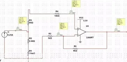 Figure49
In this structure, the output voltage would be increased by 10 times so that the voltage can be more obvious. Why I still talk about voltage here, because ADC can only measure voltage so we have to use I=U/R to get current.
Design of schematic
It is hard to draw Arduino in principle circuit so I do not combine them using principle circuit, I just jump to schematic (Figure 50). But before drawing schematic, we also need to draw symbols for Arduino (Figure 51) and operation-amplifier (Figure 52). Screen does not need a symbol as it can be connected into pins.
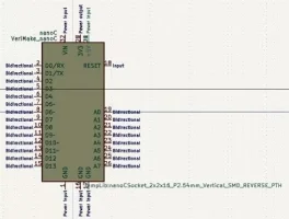 Figure51
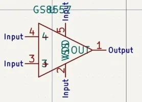 Figure52
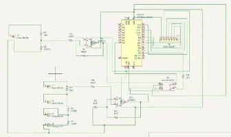 Figure50
To avoid the mistake that I did in conventional multimeter, we still use double-pole switch here. Also, the algorithm for measuring current and voltage are different so I need a pin in Arduino to tell Arduino whether we are measuring current or voltage. If it is current, the reading of pin2 would be 1 or it would be 0. In addition, we also need a pin to change the gear of current. In previous chapter, I mentioned that using Arduino has many other advantages. Now, it appears. For operation-amplifier, it needs power supply. If we use Arduino, we can use the power in Arduino so that we do not need other devices to provide power supply and GND. The last thing I want to mention is that, when you draw symbols or footprint. Please follow the instructions of the components or you would get strange results. I still made a mistake in drawing the symbol of operation-amplifier, namely I inversed + pole and – pole, which leads to a negative output of voltage.
Design of PCB
This part is completely the same as previous ones. First, draw footprints for components like Arduino (Figure 51) and operation-amplifier (Figure 52).
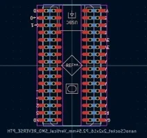 Figure51
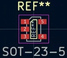 Figure52
Then, use ‘PCB from schematic’ to produce PCB, organize components and set wires (Figure 53).
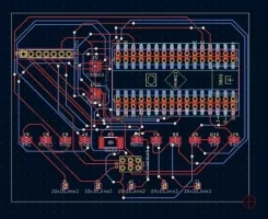 Figure53
With PCB graph, we can send it to PCB producers and wait for it (Figure 54).
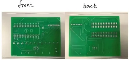 Figure54
Then, we should weld the components to PCB (Figure 55).
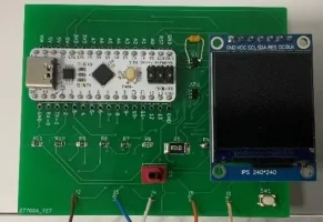 Figure55
Testing
There are two problems when we test digital multimeter. First, we output of voltage is always negative. I have analyzed this problem when I introduce schematic. It is the reason of operation-amplifier as I draw wrong poles for it. The second problem is that the measured voltage is always shaking. This is also the problem of operation-amplifier, we do not need to connect a resistor in the positive pole of operation-amplifier or the voltage might shake. After I remove the resistor, the shaking disappears (Figure 56).
 Figure56
Making a shell
This stage is simple so I do not discuss too much in this stage (Figure 57,58,63,64,65).
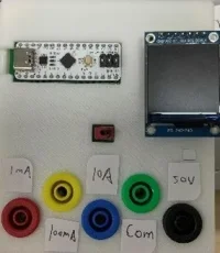 Figure57
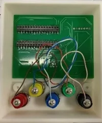 Figure58
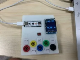 Figure63
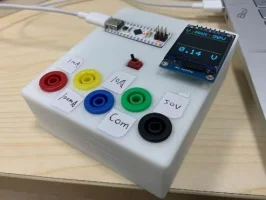 Figure64
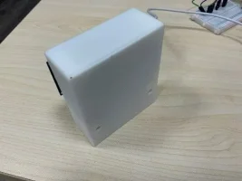 Figure65
Coding
For conventional multimeter, there is no coding but for this one, we need to code for the screen. The code is a bit complex so I do not explain too carefully in this report. If you are interested about it you can read line by line. I would show my code module by module and I would briefly introduce what is the aim of this part.
This is initiation of screen ST7789
	include <Arduino_GFX_Library.h>

	#define GFX_BL DF_GFX_BL // default backlight pin, you may replace DF_GFX_BL to actual backlight pin
	/* More dev device declaration: https://github.com/moononournation/Arduino_GFX/wiki/Dev-Device-Declaration */
	#if defined(DISPLAY_DEV_KIT)
	Arduino_GFX *gfx = create_default_Arduino_GFX();
	#else /* !defined(DISPLAY_DEV_KIT) */

	/* More data bus class: https://github.com/moononournation/Arduino_GFX/wiki/Data-Bus-Class */
	Arduino_DataBus *bus = create_default_Arduino_DataBus();

	/* More display class: https://github.com/moononournation/Arduino_GFX/wiki/Display-Class */
	Arduino_GFX *gfx = new Arduino_ST7789(bus, DF_GFX_RST, 0 /* rotation */, false /* IPS */);

	#endif /* !defined(DISPLAY_DEV_KIT) */
	/*******************************************************************************
	 * End of Arduino_GFX setting
	 ******************************************************************************/
This is the global variables I used
	int cartoon  = 0;
	 float l;
	 int vt = 0;
	 int a1t = 0;
	 float a1l;
	 int a2t = 0;
	 float a2l;
	 int intervala2 = 1000;
	 int intervala1 = 1000;
	 int interval = 1000;
	 boolean va;
	 float r = 120;
	 float v = 0;
	 boolean t1 = true;
	 float pi = 3.1415926;
	 int count1 = 0;
	 int count2 = 0;
	 int x1 = 0;
	 int x2 = 240;
	 int astate = 1;
	 boolean lastva;
	 int onlyone = 0;
	 int laststate;
	 boolean fix;
	 float a1[240];
This is the basic setting of screen and Arduino
	void setup() {
	  // put your setup code here, to run once:
	  Serial.begin(9600);
	  gfx->begin();
	  gfx->fillScreen(WHITE);
	  pinMode(A0,INPUT);
	  pinMode(2,INPUT);
	  pinMode(3,INPUT);
	  startstage1();
	  startstage2();
	//  analogReference(INTERNAL);
This is the main part of the code, which would run repetitively. The functions or procedures involved would be shown later.
	void loop() {
	  // put your main code here, to run repeatedly:
	//  startstage1();
	//  startstage2();
	  if (cartoon == 0){
	  startstage1();
	  startstage2();
	    cartoon = 1;
	  }
	  else{
	//  // ------------------------------------------
	  gfx->drawLine(0, 40, 40, 40, BLUE);
	  gfx->drawLine(40, 0, 40, 40, BLUE);
	  gfx->drawLine(40, 40, 240, 40, BLUE);
	  gfx->drawLine(0, 150, 240, 150, BLUE);
	  firststage();
	  stateshow();
	    if (laststate == 1){
	    currentmeasure1one();
	    }
	    if (laststate == 2){
	    currentmeasure1two();
	    }
	    if (laststate == 3){
	    currentmeasure1three();
	    }
	    if (laststate == 4){
	    voltagemeasure();
	    }
	  }
	    //------------------------------------------
	}
	//--------------------------------------
This the initial display of current and voltage part as the initial display is a bit different from others.
	void firststage(){
	  if (onlyone == 0){
	    lastva = amvolchange();
	    onlyone = 1;
	    if (amvolchange() == true){
	    laststate = 4;
	//    gfx->setCursor(0, 0);
	//    gfx->setTextColor(WHITE, WHITE);
	//    gfx->setTextSize(4,4,4);
	//    gfx->println("A");
	    gfx->setCursor(0, 0);
	    gfx->setTextColor(RED, RED);
	    gfx->setTextSize(4,4,4);
	    gfx->println("V");
	    gfx->setCursor(52, 0);
	    gfx->setTextColor(RED, RED);
	    gfx->setTextSize(4,4,4);
	    gfx->println("MAX:");
	    gfx->setCursor(152, 0);
	    gfx->setTextColor(RED, RED);
	    gfx->setTextSize(4,4,4);
	    gfx->println("50V");
	    }
	    else{
	    if (currentstatechange() == 2){
	      laststate = 2;
	      gfx->setCursor(52, 0);
	    gfx->setTextColor(RED, RED);
	    gfx->setTextSize(4,4,4);
	    gfx->println("MAX:");
	    gfx->setCursor(142, 10);
	    gfx->setTextColor(RED, RED);
	    gfx->setTextSize(3,3,3);
	    gfx->println("100mA");
	      }
	    if (currentstatechange() == 1){
	      laststate = 1;
	      gfx->setCursor(52, 0);
	    gfx->setTextColor(RED, RED);
	    gfx->setTextSize(4,4,4);
	    gfx->println("MAX:");
	    gfx->setCursor(152, 0);
	    gfx->setTextColor(RED, RED);
	    gfx->setTextSize(4,4,4);
	    gfx->println("10A");
	      }
	    if (currentstatechange() == 3){
	      laststate = 3;
	      gfx->setCursor(52, 0);
	    gfx->setTextColor(RED, RED);
	    gfx->setTextSize(4,4,4);
	    gfx->println("MAX:");
	    gfx->setCursor(152, 0);
	    gfx->setTextColor(RED, RED);
	    gfx->setTextSize(4,4,4);
	    gfx->println("1mA");
	      }
	//      gfx->setCursor(0, 0);
	//    gfx->setTextColor(WHITE, WHITE);
	//    gfx->setTextSize(4,4,4);
	//    gfx->println("V");
	    gfx->setCursor(0, 0);
	    gfx->setTextColor(RED, RED);
	    gfx->setTextSize(4,4,4);
	    gfx->println("A");
	      }
	    }
	}
This is the main display of current part and voltage part. It is also made up of several procedures.
	void stateshow(){
	  if (lastva != amvolchange() || currentstatechange() != laststate){
	    Serial.println(currentstatechange());
	    Serial.println(laststate);
	    Serial.println("----------------------------------------");
	    lastva = amvolchange();
	    if (amvolchange() == true){
	      if (laststate != 4){
	       gfx->fillScreen(WHITE);
	       int a1[240];
	       for (int i = 0;i < 240;i++){
	   a1[i] = 0.0;
	    }
	      }
	//    gfx->setCursor(0, 0);
	//    gfx->setTextColor(WHITE, WHITE);
	//    gfx->setTextSize(4,4,4);
	//    gfx->println("A");
	    gfx->setCursor(0, 0);
	    gfx->setTextColor(RED, RED);
	    gfx->setTextSize(4,4,4);
	    gfx->println("V");
	    gfx->setCursor(52, 0);
	    gfx->setTextColor(RED, RED);
	    gfx->setTextSize(4,4,4);
	    gfx->println("MAX:");
	//    if (laststate == 1){
	//    gfx->setCursor(152, 0);
	//    gfx->setTextColor(WHITE,WHITE);
	//    gfx->setTextSize(4,4,4);
	//    gfx->println("10A");
	//    }
	//    if (laststate == 2){
	//    gfx->setCursor(142, 10);
	//    gfx->setTextColor(WHITE,WHITE);
	//    gfx->setTextSize(3,3,3);
	//    gfx->println("100mA");
	//    }
	//    if (laststate == 3){
	//    gfx->setCursor(152, 0);
	//    gfx->setTextColor(WHITE,WHITE);
	//    gfx->setTextSize(4,4,4);
	//    gfx->println("1mA");
	//    }
	//    if (laststate == 4){
	//    gfx->setCursor(152, 0);
	//    gfx->setTextColor(WHITE,WHITE);
	//    gfx->setTextSize(4,4,4);
	//    gfx->println("10V");
	//    }
	    gfx->setCursor(152, 0);
	    gfx->setTextColor(RED, RED);
	    gfx->setTextSize(4,4,4);
	    gfx->println("50V");
	    laststate = 4;
	    }
	    else{
	       gfx->fillScreen(WHITE);
	       int a1[240];
	       for (int i = 0;i < 240;i++){
	   a1[i] = 0.0;
	    }
	//      gfx->setCursor(0, 0);
	//    gfx->setTextColor(WHITE, WHITE);
	//    gfx->setTextSize(4,4,4);
	//    gfx->println("V");
	    gfx->setCursor(0, 0);
	    gfx->setTextColor(RED, RED);
	    gfx->setTextSize(4,4,4);
	    gfx->println("A");
	    if (currentstatechange() == 1){
	      gfx->setCursor(52, 0);
	    gfx->setTextColor(RED, RED);
	    gfx->setTextSize(4,4,4);
	    gfx->println("MAX:");
	//    if (laststate == 1){
	//    gfx->setCursor(152, 0);
	//    gfx->setTextColor(WHITE,WHITE);
	//    gfx->setTextSize(4,4,4);
	//    gfx->println("10A");
	//    }
	//    if (laststate == 2){
	//    gfx->setCursor(142, 10);
	//    gfx->setTextColor(WHITE,WHITE);
	//    gfx->setTextSize(3,3,3);
	//    gfx->println("100mA");
	//    }
	//    if (laststate == 3){
	//    gfx->setCursor(152, 0);
	//    gfx->setTextColor(WHITE,WHITE);
	//    gfx->setTextSize(4,4,4);
	//    gfx->println("1mA");
	//    }
	//    if (laststate == 4){
	//    gfx->setCursor(152, 0);
	//    gfx->setTextColor(WHITE,WHITE);
	//    gfx->setTextSize(4,4,4);
	//    gfx->println("10V");
	//    }
	    gfx->setCursor(152, 0);
	    gfx->setTextColor(RED, RED);
	    gfx->setTextSize(4,4,4);
	    gfx->println("10A");
	    laststate =1;
	      }
	       if (currentstatechange() == 2){
	      gfx->setCursor(52, 0);
	    gfx->setTextColor(RED, RED);
	    gfx->setTextSize(4,4,4);
	    gfx->println("MAX:");
	//    if (laststate == 1){
	//    gfx->setCursor(152, 0);
	//    gfx->setTextColor(WHITE,WHITE);
	//    gfx->setTextSize(4,4,4);
	//    gfx->println("10A");
	//    }
	//    if (laststate == 2){
	//    gfx->setCursor(142, 10);
	//    gfx->setTextColor(WHITE,WHITE);
	//    gfx->setTextSize(3,3,3);
	//    gfx->println("100mA");
	//    }
	//    if (laststate == 3){
	//    gfx->setCursor(152, 0);
	//    gfx->setTextColor(WHITE,WHITE);
	//    gfx->setTextSize(4,4,4);
	//    gfx->println("1mA");
	//    }
	//    if (laststate == 4){
	//    gfx->setCursor(152, 0);
	//    gfx->setTextColor(WHITE,WHITE);
	//    gfx->setTextSize(4,4,4);
	//    gfx->println("10V");
	//    }
	    gfx->setCursor(142, 10);
	    gfx->setTextColor(RED, RED);
	    gfx->setTextSize(3,3,3);
	    gfx->println("100mA");
	    laststate= 2;
	      }
	      if (currentstatechange() == 3){
	      gfx->setCursor(52, 0);
	    gfx->setTextColor(RED, RED);
	    gfx->setTextSize(4,4,4);
	    gfx->println("MAX:");
	//    if (laststate == 1){
	//    gfx->setCursor(152, 0);
	//    gfx->setTextColor(WHITE,WHITE);
	//    gfx->setTextSize(4,4,4);
	//    gfx->println("10A");
	//    }
	//    if (laststate == 2){
	//    gfx->setCursor(142, 10);
	//    gfx->setTextColor(WHITE,WHITE);
	//    gfx->setTextSize(3,3,3);
	//    gfx->println("100mA");
	//    }
	//    if (laststate == 3){
	//    gfx->setCursor(152, 0);
	//    gfx->setTextColor(WHITE,WHITE);
	//    gfx->setTextSize(4,4,4);
	//    gfx->println("1mA");
	//    }
	//    if (laststate == 4){
	//    gfx->setCursor(152, 0);
	//    gfx->setTextColor(WHITE,WHITE);
	//    gfx->setTextSize(4,4,4);
	//    gfx->println("10V");
	//    }
	    gfx->setCursor(152, 0);
	    gfx->setTextColor(RED, RED);
	    gfx->setTextSize(4,4,4);
	    gfx->println("1mA");
	    laststate= 3;
	      }
	  }
	}
	}
	//----------------------------------------------
	}
	//--------------------------------------
This is the starting cartoons.
	void startstage1(){
	  while (count1 < 48){
	      Serial.println("NO");
	  gfx->drawLine(120+r*cos(pi+v), 120+r*sin(pi+v), 120+r*cos(-pi/2+v), 120+r*sin(-pi/2+v), BLUE);
	  if (t1 == true){
	  delay(500);
	  }
	  gfx->drawLine(120+r*cos(-pi/2+v), 120+r*sin(-pi/2+v), 120+r*cos(v), 120+r*sin(v), BLUE);
	  if (t1 == true){
	  delay(500);
	  }
	  gfx->drawLine(120+r*cos(v), 120+r*sin(v), 120+r*cos(pi/2+v), 120+r*sin(pi/2+v), BLUE);
	  if (t1 == true){
	  delay(500);
	  }
	  gfx->drawLine(120+r*cos(pi/2+v), 120+r*sin(pi/2+v), 120+r*cos(pi+v), 120+r*sin(pi+v), BLUE);
	  if (t1 == true){
	  delay(500);
	  }
	  gfx->drawLine(120+r*cos(pi+v+pi/4), 120+r*sin(pi+v+pi/4), 120+r*cos(-pi/2+v+pi/4), 120+r*sin(-pi/2+v+pi/4), BLUE);
	  if (t1 == true){
	  delay(500);
	  }
	  gfx->drawLine(120+r*cos(-pi/2+v+pi/4), 120+r*sin(-pi/2+v+pi/4), 120+r*cos(v+pi/4), 120+r*sin(v+pi/4), BLUE);
	  if (t1 == true){
	  delay(500);
	  }
	  gfx->drawLine(120+r*cos(v+pi/4), 120+r*sin(v+pi/4), 120+r*cos(pi/2+v+pi/4), 120+r*sin(pi/2+v+pi/4), BLUE);
	  if (t1 == true){
	  delay(500);
	  }
	  gfx->drawLine(120+r*cos(pi/2+v+pi/4), 120+r*sin(pi/2+v+pi/4), 120+r*cos(pi+v+pi/4), 120+r*sin(pi+v+pi/4), BLUE);
	  if (t1 == true){
	  delay(500);
	  }
	  gfx->drawLine(120+r*cos(pi+v), 120+r*sin(pi+v), 120+r*cos(-pi/2+v), 120+r*sin(-pi/2+v), WHITE);
	  gfx->drawLine(120+r*cos(-pi/2+v), 120+r*sin(-pi/2+v), 120+r*cos(v), 120+r*sin(v), WHITE);
	  gfx->drawLine(120+r*cos(v), 120+r*sin(v), 120+r*cos(pi/2+v), 120+r*sin(pi/2+v), WHITE);
	  gfx->drawLine(120+r*cos(pi/2+v), 120+r*sin(pi/2+v), 120+r*cos(pi+v), 120+r*sin(pi+v), WHITE);
	  gfx->drawLine(120+r*cos(pi+v+pi/4), 120+r*sin(pi+v+pi/4), 120+r*cos(-pi/2+v+pi/4), 120+r*sin(-pi/2+v+pi/4), WHITE);
	  gfx->drawLine(120+r*cos(-pi/2+v+pi/4), 120+r*sin(-pi/2+v+pi/4), 120+r*cos(v+pi/4), 120+r*sin(v+pi/4), WHITE);
	  gfx->drawLine(120+r*cos(v+pi/4), 120+r*sin(v+pi/4), 120+r*cos(pi/2+v+pi/4), 120+r*sin(pi/2+v+pi/4), WHITE);
	  gfx->drawLine(120+r*cos(pi/2+v+pi/4), 120+r*sin(pi/2+v+pi/4), 120+r*cos(pi+v+pi/4), 120+r*sin(pi+v+pi/4), WHITE);
	  t1 = false;
	  r = r - 5;
	  v = v + 0.3;
	  Serial.println("YES");
	  count1 = count1 + 1;
	  Serial.println(count1);
	  }
	  }
	void startstage2(){
	  if (count1 >= 48){
	  gfx->setCursor(60, 60);
	  gfx->setTextColor(RED, RED);
	  gfx->setTextSize(3,3,3);
	  gfx->println("ShaFeng");
	  gfx->setCursor(60, 120);
	  gfx->setTextColor(YELLOW, YELLOW);
	  gfx->setTextSize(3,3,3);
	  gfx->println("VeriMake");
	  delay(5000);
	  gfx->setCursor(60, 60);
	  gfx->setTextColor(WHITE, WHITE);
	  gfx->setTextSize(3,3,3);
	  gfx->println("ShaFeng");
	  gfx->setCursor(60, 120);
	  gfx->setTextColor(WHITE, WHITE);
	  gfx->setTextSize(3,3,3);
	  gfx->println("VeriMake");
	  }
	}
	int currentstatechange() {
	  int statecheck = 0;
	  int flag;
	  flag = digitalRead(3);
	  if (flag == 1){
	    fix = false;
	    }
	  if (fix == false){
	  if (flag == 0){
	    statecheck = 1;
	  }
	  delay(50);
	  if (flag == 0){
	    statecheck = 2;
	  }
	  if (statecheck == 2){
	        if (astate == 3){
	      astate = 1;
	      fix = true;
	    }
	    else{
	      astate = astate + 1;
	      fix = true;
	    }
	    }
	  }
	  return astate;
	}
8.This is a detection of whether you change into voltage part or current part.
	boolean amvolchange() {
	  if (digitalRead(2) == 0){
	    va= true;
	  }
	  else{
	    va = false;
	  }
	  return va;
	}
	//void finalcon(){
	//  if (amvolchange() == true){
	//    voltagemeasyre();
	//  }
	//  else{
	//    if (astate == 1){
	//      currentmeasure1one();
	//    }
	//    if (astate == 2){
	//      currentmeasure1two();
	//    }
	//    if (astate == 3){
	//      currentmeasure1three();
	//    }
	//  }
	//}
This is the display of three gears of current part. It would be used in main part of the code.
	void currentmeasure1one(){
	  float amone;
	  float c;
	  for (int i = 0;i < 240;i++){
	    gfx->drawPixel(i+1,150-a1[i]/10*110, WHITE);
	    }
	  amone = analogRead(A0);
	    c = ((amone*(4.69/1024.0)/10.0)*10.0);
	  for (int i = 0;i < 239;i++){
	    a1[i] = a1[i+1];
	    }
	  a1[239] = c;
	  for (int i = 0;i < 240;i++){
	    gfx->drawPixel(i+1,150-a1[i]/10*110, RED);
	    }
	    if (intervala1 == 1000){
	      if (a1t == 0){
	  gfx->setCursor(30, 170);
	    gfx->setTextColor(RED, RED);
	    gfx->setTextSize(5,5,5);
	    gfx->println(c);
	    a1t = 1;
	    }
	    if (a1t == 1){
	    gfx->setCursor(30, 170);
	    gfx->setTextColor(WHITE,WHITE);
	    gfx->setTextSize(5,5,5);
	    gfx->println(a1l);
	     gfx->setCursor(30, 170);
	    gfx->setTextColor(RED, RED);
	    gfx->setTextSize(5,5,5);
	    gfx->println(c);
	    a1l = c;
	    gfx->setCursor(200, 170);
	    gfx->setTextColor(RED,RED);
	    gfx->setTextSize(5,5,5);
	    gfx->println("A");
	    intervala1 = 0;
	    // unit : A
	    }
	    }
	    intervala1 = intervala1 + 100;
	}
	void currentmeasure1three(){
	  float amthree;
	  float c;
	  for (int i = 0;i < 240;i++){
	    gfx->drawPixel(i+1,150-int(a1[i]/10*110), WHITE);
	    }
	    amthree = analogRead(A0);
	  c = ((amthree*(5.0/1024.0)*1000));
	  for (int i = 0;i < 239;i++){
	    a1[i] = a1[i+1];
	    }
	  a1[239] = c;
	  for (int i = 0;i < 240;i++){
	    gfx->drawPixel(i+1,150-int(a1[i]/10*110), RED);
	    }
	  gfx->setCursor(80, 170);
	    gfx->setTextColor(RED, RED);
	    gfx->setTextSize(5,5,5);
	    gfx->println(c);
	    delay(500);
	    gfx->setCursor(80, 170);
	    gfx->setTextColor(WHITE,WHITE);
	    gfx->setTextSize(5,5,5);
	    gfx->println(c);
	    gfx->setCursor(200, 170);
	    gfx->setTextColor(WHITE,WHITE);
	    gfx->setTextSize(5,5,5);
	    gfx->println("uA");
	    // unit : uA
	}
	void currentmeasure1two(){
	  float amtwo;
	  float c;
	  for (int i = 0;i < 240;i++){
	    gfx->drawPixel(i+1,150-int(a1[i]/100*110), WHITE);
	    }
	    amtwo = analogRead(A0);
	  c = ((amtwo*(5.0/1024.0)*100));
	  for (int i = 0;i < 239;i++){
	    a1[i] = a1[i+1];
	    }
	  a1[239] = c;
	  for (int i = 0;i < 240;i++){
	    gfx->drawPixel(i+1,150-int(a1[i]/100*110), RED);
	    }
	    if (intervala2 == 1000){
	      if (a2t == 0){
	  gfx->setCursor(30, 170);
	  gfx->setTextColor(RED, RED);
	  gfx->setTextSize(5,5,5);
	  gfx->println(c);
	  a2t = 1;
	      }
	      if (a2t == 1){
	  gfx->setCursor(30, 170);
	  gfx->setTextColor(WHITE,WHITE);
	  gfx->setTextSize(5,5,5);
	  gfx->println(a2l);
	  gfx->setCursor(30, 170);
	  gfx->setTextColor(RED,RED);
	  gfx->setTextSize(5,5,5);
	  gfx->println(c);
	  a2l = c;
	  gfx->setCursor(160, 170);
	    gfx->setTextColor(RED,RED);
	    gfx->setTextSize(5,5,5);
	    gfx->println("mA");
	    intervala2 = 0;}}
	    intervala2 = intervala2 + 100;
	 // unit : mA
	}
This is the display of voltage, it is used in main part.
	void voltagemeasure(){
	  float c;
	  int volt;
	  for (int i = 0;i < 240;i++){
	    gfx->drawPixel(i+1,150-int(a1[i]/50*110), WHITE);
	    }
	  volt = analogRead(A0);
	  c = volt*(4.69/1024.0)*10.01;
	  for (int i = 0;i < 239;i++){
	    a1[i] = a1[i+1];
	    }
	  a1[239] = c;
	//  for (int i = 0;i < 240;i++){
	//    Serial.println(c4[i]);
	//    }
	  for (int i = 0;i < 240;i++){
	    gfx->drawPixel(i+1,150-int(a1[i]/50*110), RED);
	    }
	    if (interval == 1000){
	      if(vt == 0){
	  gfx->setCursor(30, 170);
	  gfx->setTextColor(RED, RED);
	  gfx->setTextSize(5,5,5);
	  gfx->println(c);
	  vt = 1;}
	  if (vt == 1){
	  gfx->setCursor(30, 170);
	  gfx->setTextColor(WHITE,WHITE);
	  gfx->setTextSize(5,5,5);
	  gfx->println(l);
	  gfx->setCursor(30, 170);
	  gfx->setTextColor(RED, RED);
	  gfx->setTextSize(5,5,5);
	  gfx->println(c);
	  l = c;
	  gfx->setCursor(200, 170);
	    gfx->setTextColor(RED,RED);
	    gfx->setTextSize(5,5,5);
	    gfx->println("V");
	    interval = 0;
	  }
	    }
	    interval = interval + 100;
	  // unit : V
	}
Last, I would show the display of the screen. I set several starting cartoons for the digital multimeter (Figure 59,60).
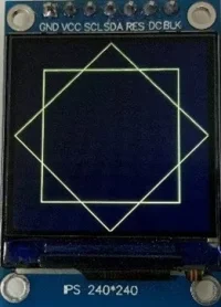 Figure59
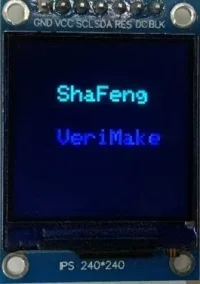 Figure60
Figure 61 is the measuring of voltage and Figure 62 is for current.
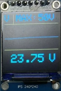 Figure61
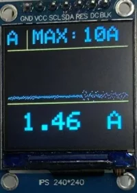 Figure62
The top of left tells you it is current gear or voltage gear. Near it, the ‘MAX’ tells you what the maximum range of the gear. The middle part is a wave graph of the quantity. And the bottom is the value get.
Further plan
The main task is reached in this project. Both analogue multimeter and digital multimeter can measure voltage and current. And we also succeed in setting different dears for both quantity. However, because of the precision of the components we used so there is percentage error, especially for those quantities which use small resistance, such as current. For quantities like voltage, this is not a great problem as the resistance used is very larger so small percentage difference will not have an obvious effect on the output. In addition, the output of current is still shaking so we need other method to smooth the current wave. There is an interesting phenomenon, namely even I do not connect circuit to multimeter there is still readings, though the readings are very small so we need an algorithm to filter the extra voltage.
Conclusion
I learnt a lot in this project. I studied the basic principle of how amperemeter and voltmeter work and, in the designing of conventional multimeter, I could apply the knowledge that I learnt in my test book into real-life application (Such as the knowledge about electricity and magnetism). Also, I learnt how to use Multisim to draw principle circuit and how to use KiCad to draw schematic and PCB, as well as symbols and footprints. Before the designing of digital multimeter, through research, I also generally studied how ADC and operation-amplifier work. In the designing of screen, I did a lot of coding so my coding ability is also improved a lot. In short, the whole project is electronic and practical so my understanding about electronic engineering increases a lot. The most important point I learnt is that electronic engineering is a subject to use electronic devices to solve real-life problems. From the problems I met, I learnt that making mistake is not terrible, the more important is that we need to analysis problem and think about how to solve it.
 网站备案号:ICP备16046599号-1