Introduction
Why to choose this project
I started learning Physics from Grade 7 and, in Physics, there is an important chapter called ‘Electricity’. Many quantities, such as current and voltage, are required to be measured in practical in this chapter. In my middle school, I usually used amperemeter (Figure 1) to measure current and voltmeter (Figure 2) was commonly used to measure potential difference. Both of them are called analog meters or conventional meters. However, in my high school, analog meters were replaced by multimeters (Figure 3), also called digital meters. Compared with conventional meters, multimeters can measure both current and potential difference and even resistance of a component can be measured. Also, common multimeters can have several gears for one quantity. For example, if you want to measure current, you can either choose a gear of maximum range of 10A or a gear of maximum range of 1A. In this project, I want to design and produce a conventional meter and a multimeter by myself to explore how these equipment works. Also, I would mix some personal ideas to these equipment to make them more powerful.
It is essential to mention that, for this project, I draw principle circuit using Multisim (A software to draw principle circuit) (https://www.multisim.com/) , draw schematic and PCB (Printed circuit board) using KiCad (A software to draw schematic and PCB) (https://componentsearchengine.com/library/kicad?gclid=EAIaIQobChMIyOyf2p_r-AIV5JNmAh2FQwoOEAAYASAAEgLkNPD_BwE) , buy components from Jia Li Chuang (A company to sell electronic components)(https://www.jlc.com/) .
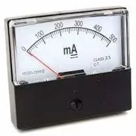 Figure1
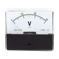 Figure2
 Figure3
How to do this project
This project consists of two main stages. One is designing a conventional multimeter and the second stage is designing a digital multimeter. For each stage, I would mention background knowledge needed and analysis the principle of the equipment. Also, I would show the circuits, schematics and PCBs used in this project. Each multimeter might have several versions as there may be some problems in previous ones, so I would demonstrate all of them and show how I finish it step by step.
Design of conventional multimeter
Analysis of how conventional amperemeter and voltmeter work
First, let me show a conventional amperemeter (Figure 4) again.
Figure4
There is a needle which can deflect and, as the needle deflects, it can point to a value on the dial. If we remove the shell of the amperemeter, we can see that inside the amperemeter, there is an electrical and magnetic structure (Figure 5). Before I introduce how it works, I have to mention a theory, namely current will experience a force in a magnetic field (http://physics.bu.edu/~duffy/py106/MagForce.html). Moreover, I would briefly explain why it is true. It is proved that there is a magnetic field around a current (the prove of this theory is beyond my knowledge) so when current is in a magnetic field, the produced field will interact with the existing one like Figure 6 and current will experience a force. Then, let me go back to how the meters work. The basic principle of amperemeter and voltmeter is similar so I would introduce their similarities first and then I would discuss their difference. Whatever it is voltmeter or amperemeter, as soon as you connect it into a circuit, current will flow into the meter. Then, through am equation F=BIL (B is the magnetic flux density,I is current,L is the perpendicular length of current in the magnetic field), we can see that the force experience is directly proportional to the magnitude of current. Then, the force will produce a torque to the needle and push it to deflect. As a result, the degree of the deflection is also proportional to the magnitude of the current. That is the basic principle of how it works.
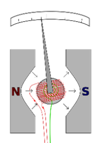 Figure5
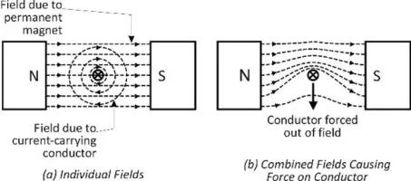 Figure6
Second, let me discuss what is the difference between amperemeter and voltmeter. Commonly, we know that amperemeter must be connected in series into a circuit (Figure 7) while voltmeter must be connected in parallel (Figure 8). Why is this. If we do more research about these meters, we can see that amperemeter usually has small resistance and voltmeter usually has huge resistance because, inside the meters, apart from a component like Figure 5, there are also some resistors connected in series or parallel (For amperemeter it is parallel (Figure 9), for voltmeter it is series (Figure 10)). I would use my diagram to explain why the internal structure is like this. In conclusion, both of amperemeter and voltmeter use ‘current will experience a force in a magnetic field’ to measure electrical quantities, the only difference is their internal structure. Also, from this research, we can feel that usage depends on structure. If you want to know more detailed information about amperemeter and voltmeter, you can go to (https://www.electronics-tutorials.ws/blog/ammeter.html) to learn more about amperemeter and go to (https://www.electronics-tutorials.ws/blog/voltmeter.html) to learn more about voltmeter.
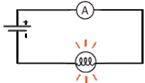 Figure7
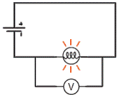 Figure8
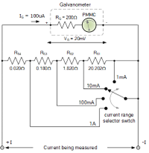 Figure9
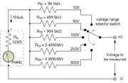 Figure10
Circuit for conventional multimeter
A general introduction of what I want to do
As I mentioned in previous page, the basic electrical and magnetic structure for amperemeter and voltmeter is completely same so in this project, I want to combine voltmeter and amperemeter into a single equipment. Also, I want to set several gears for this multimeter so that users can choose most suitable gear to get a clearer reading (For example, the current you want to measure is 0.5A. If you use a gear of maximum range of 10A, it will only deflect about 4.5 degree. If you use a gear of maximum range of 1A, it will deflect 45 degree).
Design for amperemeter
The electrical and magnetic component consists of coils, a needle and a magnet. The coil is connected to the circuit so coil is also a part of the circuit. As a result, the resistance of the circuit cannot be ignored. The first step is to measure the resistance of the coil. Through R=U/I, we can apply a potential difference to the coil and measure the current passing through it. Then, different potential difference can be applied to get a more accurate value. I did a measurement like this (Figure 11) with a coil that I would use in this project (Figure 12,13). I recorded the data and use data fitting in excel to calculate the resistance of the coil. Because of the unit of current I used was mA, so the final resistance was 1.4677KΩ which is 1468Ω.
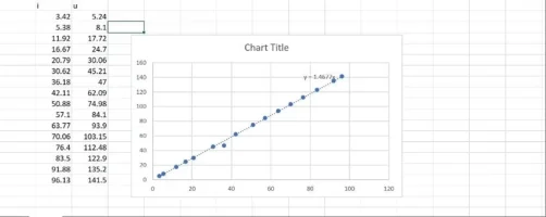 Figure11
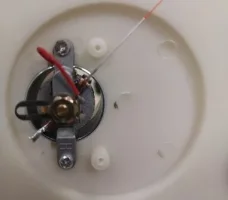 Figure12
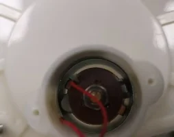 Figure13
If we just connect the coil to a normal circuit, there would be little deflection as the resistance is too large. As a result, we must connect resistors in parallel with the coil to reduce the overall resistance of the amperemeter so my circuit would look like this (Figure 14). You might ask a question why I connected so many resistors and switches. That is what I mentioned before. I want to set several gears for the multimeter. Through my experiment, I found that the maximum current that the coil can hold is 0.1mA, if the current experienced by the coil is greater that 0.1mA, then the needle point out of the dial. With this information, we can easily determine the magnitude of the resistor connected. For example, if I hope that I can measure a maximum of 5mA. This means that when I connect the amperemeter to a circuit with 1A, the current flowing through the coil is 0.1mA because the resistors connected parallel with the coil might share some current with it. As they are in parallel, their potential difference is the same so we use U=IR to get the potential difference in this situation is 0.147V. The coil only takes 0.1mA so the resistor will take 4.9mA. Using R=U/I, we can get that the resistance required is 30Ω. Following the same principle, we can calculate the resistance required by other gears. Last, it is important to take care that, as gears are different, we must make a dial by ourself to satisfy different gears.
图14Figure14
Design for voltmeter
For voltmeter, the only difference is that resistors are connected in series with the coil because resistors in series can share the voltage with coil. From U=IR, we can calculate that the maximum voltage that can coil can hold is 0.147V. As a result, if we hope that the voltmeter can measure a maximum voltage of 10V, the resistor must take 9.853V which means its resistance is 98530Ω (almost 100KΩ). Following the same principle, we can calculate the resistance required by other gears. The final circuit would look like this (Figure 15). You might ask if we connect such a huge resistance with the coil, the overall resistance of the voltmeter would be extremely huge. Yes, it is. But it does not matter as voltmeter is connected in parallel with circuit. If the resistance of the voltmeter is very high, it would not affect the circuit too much.
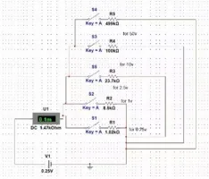 Figure15
First version of combination of voltmeter and ampere
Principle circuit for the first combination
Why I say it is the first combination? Because I made a mistake in the design of the combined graph, I would analysis the mistake in the test part. And, in this paragraph, I would still use the wrong one because this is the process of learning. The correct graph is in the second version. The first draft is like Figure 16. The combination of voltmeter and ampere means only one coil is shared. If it is separated meters, each one can contain a coil. But, to connect them, they must share it. After realizing this, the problem now is how to deal with two groups of resistors. One would be connected in series with the coil (voltmeter) and the other group would be connected in parallel with it (ampere). To achieve this goal, I choose to use a SPDT switch (single pole double throw switch).
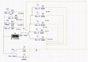 Figure16
Design of schematic
There is only one change made to the schematic. From the circuit, we can see that I set 4 gears for amperemeter and 5 gears for voltmeter but it is impossible for me to equip so many switches and I hope that only two switches can be used. Finally, I choose to use a rotary switch called C508440 (Figure 17)(https://atta.szlcsc.com/upload/public/pdf/source/20200407/C508442_06221D97AB66BB11D47530C9AEBA3201.pdf). For this switch, you can just rotate it to change gears which is convenient. However, there is no symbol for this component in the schematic of KiCad so I need to draw it by myself (Figure 18). Also, I need to draw a symbol for the coil used (Figure 19). With these preparations, we can start drawing our schematic (Figure 20).
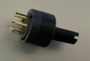 Figure17
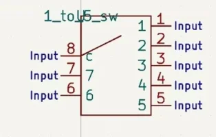 Figure18
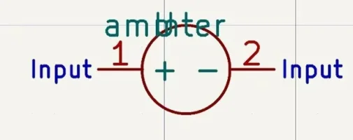 Figure19
 Figure20
Design of PCB
After drawing schematic, there is function in KiCad called ‘Update PCB from schematic’, which can convert your schematic into PCB directly. However, we still need to set footprint for each component used in schematic so that it can be displayed in PCB. For components like resistors, we can use ready-made footprint in KiCad but we still need to draw footprint for components like rotary switch (Figure 21), coil (Figure 22), SPDT switch (Figure 24) and testing lines (a place to connect multimeter with circuit) (Figure 23). When we draw footprints for these components, we must follow the instructions in the introduction of the components you bought, especially making sure your pin number and poles are correct, or there would be something wrong with your PCB. When we finish drawing footprint, we can create our PCB (Figure 25). So far, our PCB just demonstrate some components and we need to organize them and set wires to connect them (Figure 26).
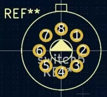 Figure21
 Figure22
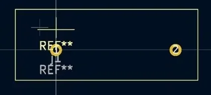 Figure23
 Figure24
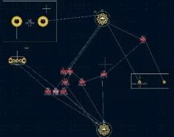 Figure25
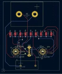 Figure26
When we finish designing the PCB and making sure that the graph has no errors, we can send the graph to PCB producers and wait for it (Figure 27).
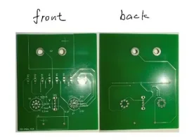 Figure27
The next step is to weld the components on the PCB (Figure 28). I try to place the coil into the PCB but it seems that the holes are too close to each other so I have to polish them.
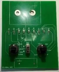 Figure28
Testing
This is the most important part. There are some errors for both measuring current and voltage. First, the deflection of current is much larger that my expectation and if I do not set current part into initial gear, there would be no deflection for voltage part. The second problem is strange. For the first problem it might be caused the error of the magnitude of resistors (The wires might have resistance. The coil has resistance of 1400Ω and resistors for measuring voltage have huge resistance so the resistance of wires has little effect to them. But the resistance of resistors for measuring current is low so the extra resistance might have a large percentage increase to the magnitude of them which result in a larger current flowing through the coil ). But for the second problem, only current part can affect voltage part and voltage part will not affect current part. To find out the source of the error, I must go back to my principle circuit (Figure 20).
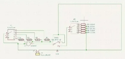 Figure20
Finally, it is the problem of the switch. If you analysis the circuit, you can find that if switch is turned up, resistors in series (resistors of voltage part) are separated which is correct. However, if switch is turned down, resistors in parallel (resistors of current part) are still connected in the circuit so this might be the cause of the second problem. As we know, the resistors for measuring current have low resistance so if they are connected in parallel, most current will flow through them instead of flowing through coil. As a result, there is little deflection for voltage part if current part is not turned to initial gear.
Second version of combination of voltmeter and ampere
Principle circuit for the second combination
Because only one coil is used in this multimeter so the main structure of this multimeter cannot be changed and the only component we can alternate is the switch. We should use a switch that can either connecting voltage part and separating current part or connecting current part and separating voltage part. To achieve this, I go back to electronic component market and find a new switch called double-pole switch (Figure 29) (file:///C:/Users/user/Downloads/C1122348_%E5%BC%80%E5%85%B3_2021-03-25%20(2).PDF).
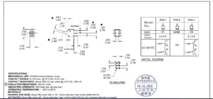 Figure29
For this kind of switch, you can find that there are two keys inside it and they will act completely the same which means either both of them turns up or both of them turn down. With it, we can draw a new principle circuit (Figure 30).
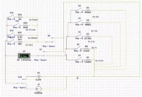 Figure30
For this circuit, if you turn the switch up, current part is connected and voltage part is separated, if you turn the switch down, voltage part is connected and current part is separated.
Design of schematic
With the corrected principle circuit, we could draw a new schematic (Figure 31).
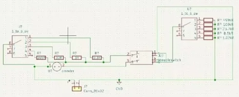 Figure31
Almost everything in this schematic is the same as the previous one, the only difference is the switch so we need to draw a new symbol for it (Figure 32).
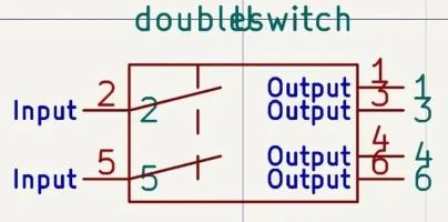 Figure32
I made a mistake in drawing the symbol again and the problem would be seen in testing part.
Design of PCB
Before creating the PCB, we need to design a new footprint for the switch (Figure 33). With the schematic, then we can create our PCB (Figure 34).
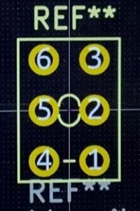 Figure33
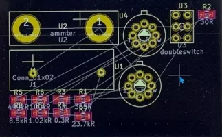 Figure34
Next, we need to organize them and set wires (Figure 35).
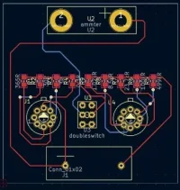 Figure35
Then, we send the PCB graph to PCB producers and wait for the new one (Figure 36).
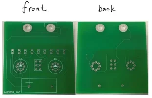 Figure36
Then, it is time to weld components into the PCB (Figure 37).
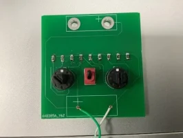 Figure37
Testing
We are surprised to find that for the new board, neither measuring current nor measuring voltage show deflection. This is strange and the only cause would be that there is some thing broken in the circuit. After analyzing, it is the problem of the symbol of the double-pole switch.
When we draw symbols, we need to set pins for the component so that the component can be connected into the circuit and the side with ‘input’ must be outside the component because it is where component can be connected. But if you check my symbol (Figure 32). You can find that the output side is inside the component so actually the switch is not connected into the circuit which result in no deflection. And correct symbol should be like Figure 38.
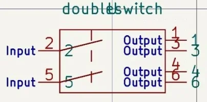 Figure32
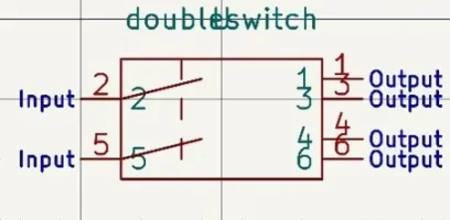 Figure38
However, I do not want to redraw a new PCB and wait for it again so there is a method, namely we can connect the PCB by hand (Figure 39). It looks ugly but it does work, after connecting two wires, all function of the PCB works well.
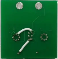 Figure39
Draw a dial and make a shell
As the internal circuit is designed by myself so the degree of deflection is a bit different and we need to draw a new dial depends on the degree of the deflection of this multimeter (Figure 40).
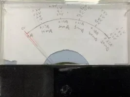 Figure40
Then the last step for this stage is to produce a shell for the multimeter to make it looks more beautiful (Figure 41, 42,66,67,68).
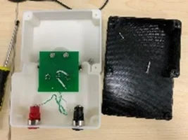 Figure41
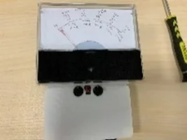 Figure42
Figure66
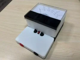 Figure67
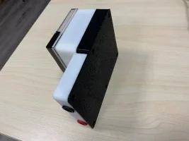 Figure68
 网站备案号:ICP备16046599号-1