赤兔板CH32V307蓝牙模块教程(上)
前言
说是教程,其实算个人的学习笔记,这其中也涉及到和赤菟板上的LCD屏幕的互动。在学习这个蓝牙模块的途中也遇到不少问题,也难怪论坛上不少人都在问相关问题。老规矩,没接触过赤菟板的可以移步论坛的赤菟教程目录。本次的教程将分为上中下三篇说明蓝牙模块的使用。
前置资料与工具
这部分的资料和工具基本上都可以在沁恒的官网上找到(当然本文的最后也会贴):传送门
1.虚拟串口管理器
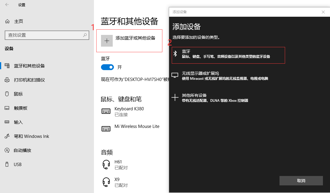
相信很多同学都被卡在这里了,明明已经搜到蓝牙,也连接上了,为什么在设备管理器的端口(COM和LPT)中根本找不到蓝牙串口,他并没有产生新的蓝牙串口。这好像是因为Windows更新的时候把这个更新掉了,所以我们需要用虚拟串口,即进入沁恒官网(上方已贴出)下载下图所示的BLEComWin.ZIP。

装好压缩包里面的软件之后直接打开,如下图步骤创建蓝牙虚拟串口。(注意断开你之前在电脑蓝牙设置里面的蓝牙连接,同时只能与一个设备建立连接)
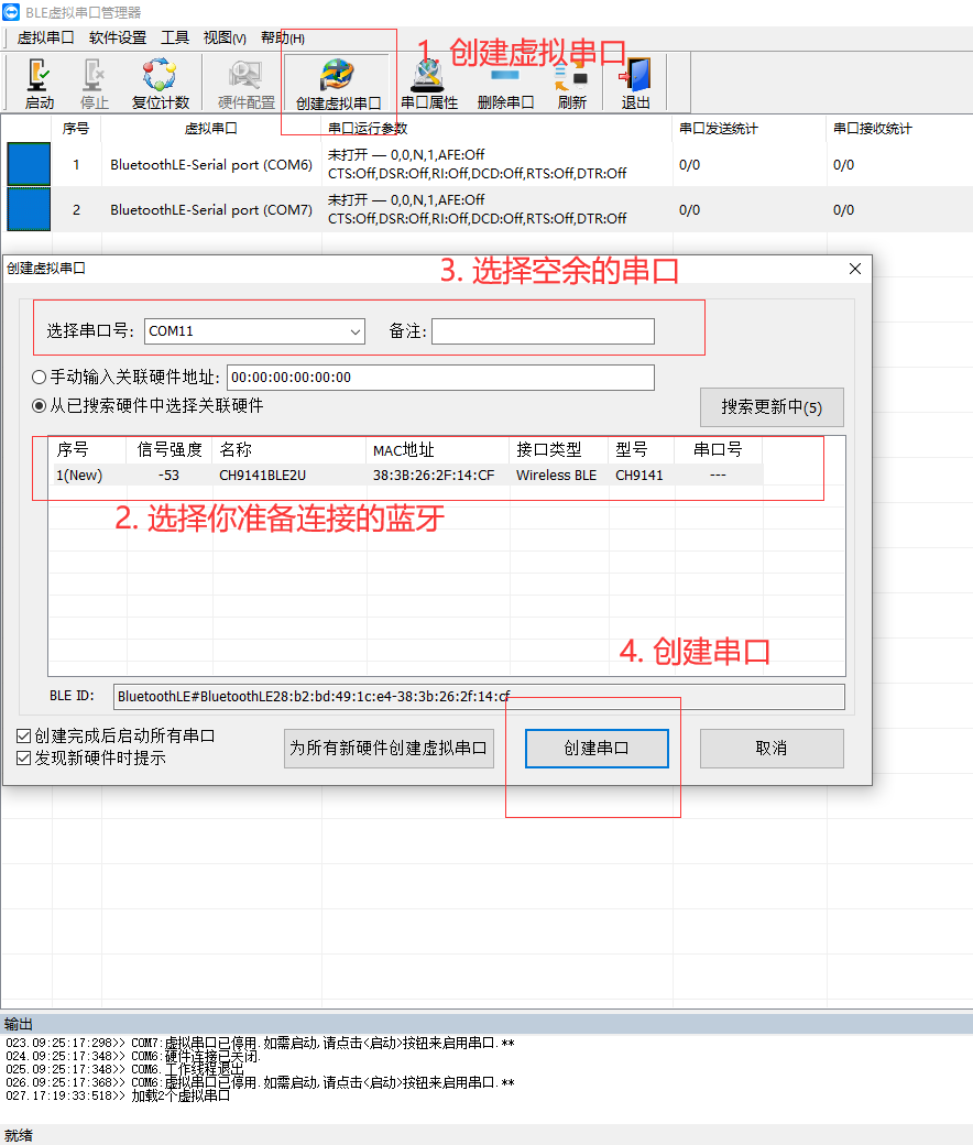
创建好虚拟串口后,如果板子没有和其他设备连接的话会自动连接,左上角的启动和停止是用来切断与板子的蓝牙连接的,之后的主从机连接时会用到的。
2.WCH蓝牙调试助手
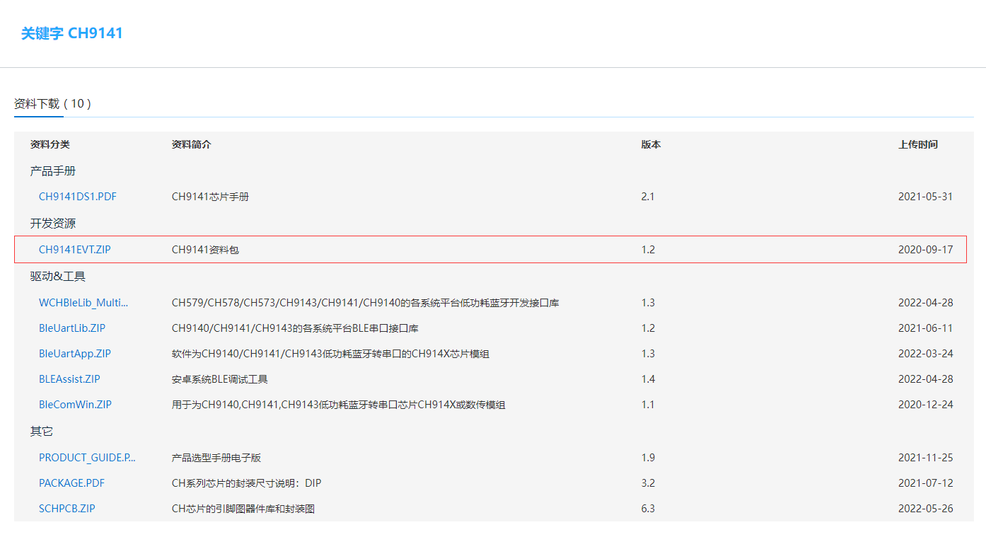
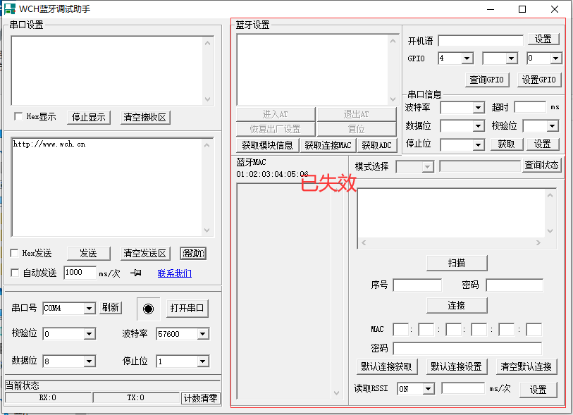
这个压缩包里面CH9141EVT使用说明和TOOLS里面的WCH蓝牙调试助手是需要用到的,但是使用说明里面和AT指令相关的内容已经完全失效,已经汇报给了沁恒官方。这个蓝牙调试助手仅可通过蓝牙串口发送数据,通过WCHLink串口接收数据,而通过WCHLink串口向蓝牙串口发送的数据好像板子就接收不到,其他的串口助手(这里沿用论坛CH549资料包里面带的串口助手)可正常收发数据。这里可能也是部分同学碰到问题的原因。(波特率记得调为115200,下图未调仍处于默认状态)
3.CH9141数据手册
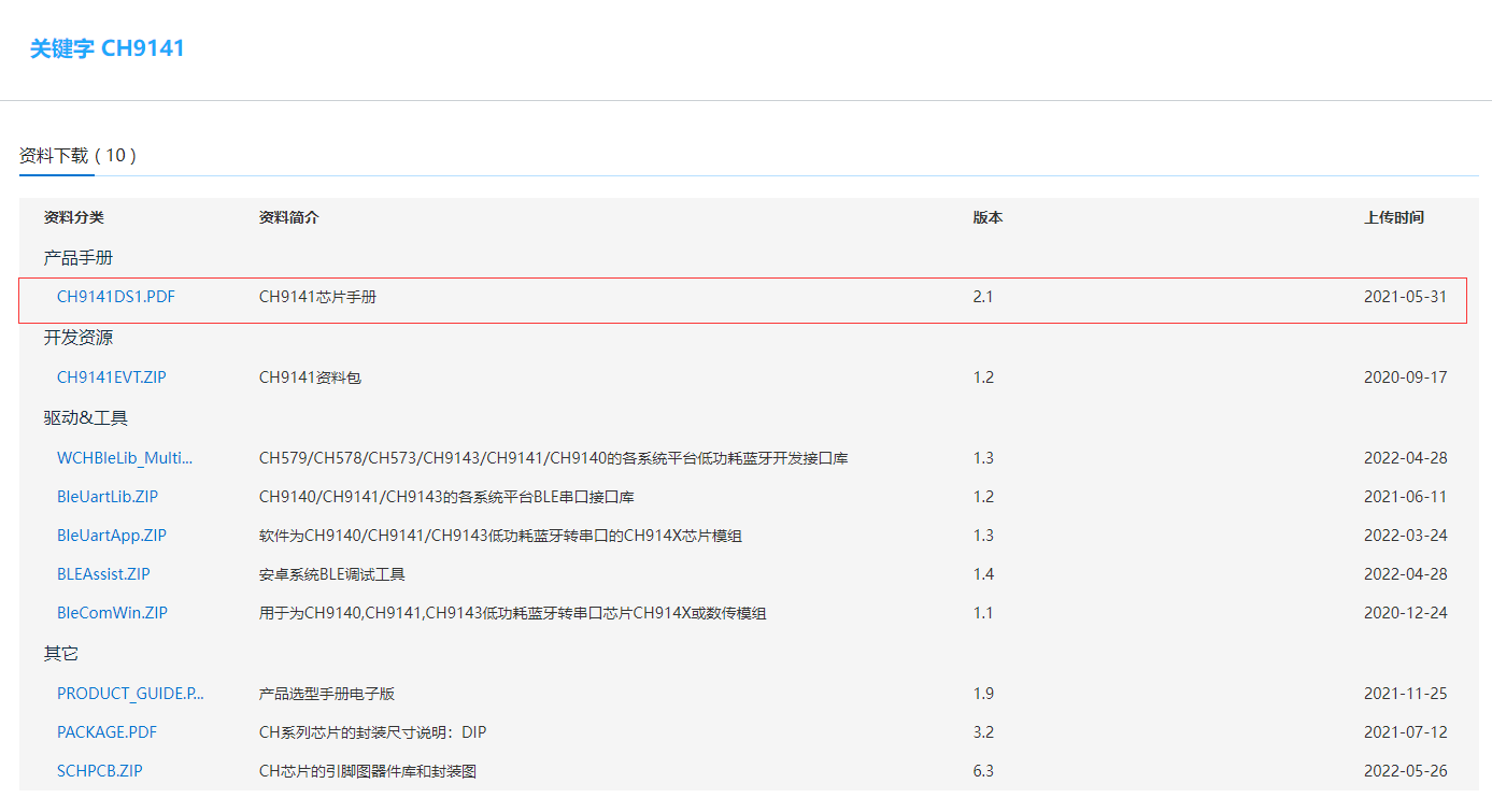
由数据手册可以知道CH9141是一款蓝牙串口透传芯片,芯片支持广播模式、主机模式和从机模式,支持蓝牙BLE4.2。支持串口AT配置和在从机模式下的蓝牙通信配置,支持MODEM联络信号,并提供通用GPIO、同步GPIO、ADC采集功能,串口波特率最高1Mbps。蓝牙从机模式下可设置蓝牙名称、厂商信息等参数,可通过APP或者串口命令轻松配置,方便快捷。
4.手机端蓝牙调试器

用手机端连接时,需要通过蓝牙调试软件与CH9141通信注意CH9141透传服务的UUID为0000fff0,其中CH9141的TX为0000fff1,RX为0000fff2。配置不正确可以连接但不能通信。
上图这个app可以在应用市场下载到,注意版本,如果无上图设置参数的齿轮图标,请更新到最新版,相关博客:传送门。
当然也可以用沁恒官方的BLE调试APP,配置比较详细,适合复杂调试:传送门
准备程序
这部分即主程序的各个组成部分,分别驱动各个模块。
1.LCD屏幕显示
LCD.h
#ifndef __LCD_H
#define __LCD_H

#include"debug.h"
#include"stdlib.h"

#define  LCD_CMD         ((u32)0x6001FFFF)
#define  LCD_DATA        ((u32)0x60020000)

/* PWM Output Mode Definition */
#define PWM_MODE1   0
#define PWM_MODE2   1

/* PWM Output Mode Selection */
#define PWM_MODE PWM_MODE1
//#define PWM_MODE PWM_MODE2


#define  delay_ms(x)  Delay_Ms(x)
#define  delay_us(x)  Delay_Us(x)


#define LCD_W 240
#define LCD_H 240

//POINT_COLOR
#define WHITE            0xFFFF
#define BLACK            0x0000
#define BLUE             0x001F
#define BRED             0XF81F
#define GRED             0XFFE0
#define GBLUE            0X07FF
#define RED              0xF800
#define MAGENTA          0xF81F
#define GREEN            0x07E0
#define CYAN             0x7FFF
#define YELLOW           0xFFE0
#define BROWN            0XBC40
#define BRRED            0XFC07
#define GRAY             0X8430
#define GRAY175          0XAD75
#define GRAY151          0X94B2
#define GRAY187          0XBDD7
#define GRAY240          0XF79E
#define LGRAY            0XC618


void lcd_clear(u16 color);
void lcd_address_set(u16 x1, u16 y1, u16 x2, u16 y2);
void lcd_set_color(u16 back, u16 fore);

void lcd_draw_point(u16 x, u16 y);
void lcd_draw_point_color(u16 x, u16 y, u16 color);
void lcd_draw_circle(u16 x0, u16 y0, u8 r);
void lcd_draw_line(u16 x1, u16 y1, u16 x2, u16 y2);
void lcd_draw_rectangle(u16 x1, u16 y1, u16 x2, u16 y2);
void lcd_fill(u16 x_start, u16 y_start, u16 x_end, u16 y_end, u16 color);

void lcd_show_num(u16 x, u16 y, u32 num, u8 len, u32 size);
void lcd_show_string(u16 x, u16 y, u32 size, const char *fmt, ...);
void lcd_show_image(u16 x, u16 y, u16 length, u16 wide, const u8 *p);

void lcd_init(void);
void LCD_SetBrightness(u8 brightness);

void lcd_enter_sleep(void);
void lcd_exit_sleep(void);
void lcd_display_on(void);
void lcd_display_off(void);

#endif
该.h文件为LCD屏幕显示的头文件,定义了屏幕各个参数,具体函数看.c文件。
LCD.c
#include "lcd.h"
#include "stdlib.h"
#include "font.h"
#include "stdarg.h"


#define LCD_CLEAR_SEND_NUMBER 5760

u16 BACK_COLOR = BLACK, FORE_COLOR = WHITE;

void lcd_write_cmd(const u8 cmd)
{
    *(__IO u8*)LCD_CMD=cmd;
}

void lcd_write_data(const u8 data)
{
    *(__IO u8*)LCD_DATA=data;
}

void lcd_write_half_word(const u16 da)
{
    *(__IO u8*)LCD_DATA=(u8)(da>>8);
    *(__IO u8*)LCD_DATA=(u8)da;
}

u8 lcd_read_data(void)
{
    vu8 ram;
    ram = *(__IO u8*)LCD_DATA;
    return ram;
}

u8 lcd_read_reg(const u8 reg)
{
    lcd_write_cmd(reg);
    delay_us(5);
    return lcd_read_data();

}

void lcd_fsmc_init(void)
{
    GPIO_InitTypeDef GPIO_InitStructure={0};
    FSMC_NORSRAMInitTypeDef  FSMC_NORSRAMInitStructure={0};
    FSMC_NORSRAMTimingInitTypeDef  readWriteTiming={0};
    FSMC_NORSRAMTimingInitTypeDef  writeTiming={0};

    RCC_AHBPeriphClockCmd(RCC_AHBPeriph_FSMC,ENABLE);
    RCC_APB2PeriphClockCmd(RCC_APB2Periph_GPIOB|RCC_APB2Periph_GPIOD|RCC_APB2Periph_GPIOE,ENABLE);

    GPIO_InitStructure.GPIO_Pin = GPIO_Pin_0|GPIO_Pin_1|GPIO_Pin_4|GPIO_Pin_5|GPIO_Pin_14|GPIO_Pin_15;
    GPIO_InitStructure.GPIO_Mode = GPIO_Mode_AF_PP;
    GPIO_InitStructure.GPIO_Speed = GPIO_Speed_50MHz;
    GPIO_Init(GPIOD, &GPIO_InitStructure);

    GPIO_InitStructure.GPIO_Pin = GPIO_Pin_7|GPIO_Pin_8|GPIO_Pin_9|GPIO_Pin_10;
    GPIO_InitStructure.GPIO_Mode = GPIO_Mode_AF_PP;
    GPIO_InitStructure.GPIO_Speed = GPIO_Speed_50MHz;
    GPIO_Init(GPIOE, &GPIO_InitStructure);

    /*   RS--D12  */
    GPIO_InitStructure.GPIO_Pin = GPIO_Pin_12;
    GPIO_InitStructure.GPIO_Mode = GPIO_Mode_AF_PP;
    GPIO_InitStructure.GPIO_Speed = GPIO_Speed_50MHz;
    GPIO_Init(GPIOD, &GPIO_InitStructure);

    /* CS: PD7*/
    GPIO_InitStructure.GPIO_Pin = GPIO_Pin_7;
    GPIO_InitStructure.GPIO_Mode = GPIO_Mode_Out_PP;
    GPIO_InitStructure.GPIO_Speed = GPIO_Speed_50MHz;
    GPIO_Init(GPIOD, &GPIO_InitStructure);
    GPIO_ResetBits(GPIOD,GPIO_Pin_7);

    readWriteTiming.FSMC_AddressSetupTime = 0x01;
    readWriteTiming.FSMC_AddressHoldTime = 0x00;
    readWriteTiming.FSMC_DataSetupTime = 0x0f;
    readWriteTiming.FSMC_BusTurnAroundDuration = 0x00;
    readWriteTiming.FSMC_CLKDivision = 0x00;
    readWriteTiming.FSMC_DataLatency = 0x00;
    readWriteTiming.FSMC_AccessMode = FSMC_AccessMode_A;

    writeTiming.FSMC_AddressSetupTime = 0x00;
    writeTiming.FSMC_AddressHoldTime = 0x00;
    writeTiming.FSMC_DataSetupTime = 0x03;
    writeTiming.FSMC_BusTurnAroundDuration = 0x00;
    writeTiming.FSMC_CLKDivision = 0x00;
    writeTiming.FSMC_DataLatency = 0x00;
    writeTiming.FSMC_AccessMode = FSMC_AccessMode_A;

    FSMC_NORSRAMInitStructure.FSMC_Bank = FSMC_Bank1_NORSRAM1;

    FSMC_NORSRAMInitStructure.FSMC_DataAddressMux = FSMC_DataAddressMux_Disable;
    FSMC_NORSRAMInitStructure.FSMC_MemoryType =FSMC_MemoryType_SRAM;
    FSMC_NORSRAMInitStructure.FSMC_MemoryDataWidth = FSMC_MemoryDataWidth_8b;
    FSMC_NORSRAMInitStructure.FSMC_BurstAccessMode =FSMC_BurstAccessMode_Disable;
    FSMC_NORSRAMInitStructure.FSMC_WaitSignalPolarity = FSMC_WaitSignalPolarity_Low;
    FSMC_NORSRAMInitStructure.FSMC_AsynchronousWait=FSMC_AsynchronousWait_Disable;
    FSMC_NORSRAMInitStructure.FSMC_WrapMode = FSMC_WrapMode_Disable;
    FSMC_NORSRAMInitStructure.FSMC_WaitSignalActive = FSMC_WaitSignalActive_BeforeWaitState;
    FSMC_NORSRAMInitStructure.FSMC_WriteOperation = FSMC_WriteOperation_Enable;
    FSMC_NORSRAMInitStructure.FSMC_WaitSignal = FSMC_WaitSignal_Disable;
    FSMC_NORSRAMInitStructure.FSMC_ExtendedMode = FSMC_ExtendedMode_Enable;
    FSMC_NORSRAMInitStructure.FSMC_WriteBurst = FSMC_WriteBurst_Disable;
    FSMC_NORSRAMInitStructure.FSMC_ReadWriteTimingStruct = &readWriteTiming;
    FSMC_NORSRAMInitStructure.FSMC_WriteTimingStruct = &writeTiming;
    FSMC_NORSRAMInit(&FSMC_NORSRAMInitStructure);
    FSMC_NORSRAMCmd(FSMC_Bank1_NORSRAM1, ENABLE);

}

/*******************************************************************************
* Function Name  : TIM1_PWMOut_Init
* Description    : Initializes TIM1 PWM output.
* Input          : arr: the period value.
*                  psc: the prescaler value.
*                                    ccp: the pulse value.
* Return         : None
*******************************************************************************/
void TIM1_PWMOut_Init( u16 arr, u16 psc, u16 ccp )
{
    TIM_OCInitTypeDef TIM_OCInitStructure;
    TIM_TimeBaseInitTypeDef TIM_TimeBaseInitStructure;

    TIM_TimeBaseInitStructure.TIM_Period = arr;
    TIM_TimeBaseInitStructure.TIM_Prescaler = psc;
    TIM_TimeBaseInitStructure.TIM_ClockDivision = TIM_CKD_DIV1;
    TIM_TimeBaseInitStructure.TIM_CounterMode = TIM_CounterMode_Up;
    TIM_TimeBaseInit( TIM1, &TIM_TimeBaseInitStructure );

#if (PWM_MODE == PWM_MODE1)
    TIM_OCInitStructure.TIM_OCMode = TIM_OCMode_PWM1;

#elif (PWM_MODE == PWM_MODE2)
    TIM_OCInitStructure.TIM_OCMode = TIM_OCMode_PWM2;
#endif

    TIM_OCInitStructure.TIM_OutputState = TIM_OutputState_Disable;
    TIM_OCInitStructure.TIM_OutputNState = TIM_OutputNState_Enable;
    TIM_OCInitStructure.TIM_Pulse = ccp;
    TIM_OCInitStructure.TIM_OCNPolarity = TIM_OCNPolarity_High;
    TIM_OC2Init( TIM1, &TIM_OCInitStructure );

    TIM_CtrlPWMOutputs( TIM1, ENABLE );
    TIM_OC2PreloadConfig( TIM1, TIM_OCPreload_Disable );
    TIM_ARRPreloadConfig( TIM1, ENABLE );
    TIM_Cmd( TIM1, ENABLE );
}

void lcd_gpio_init(void)
{

    GPIO_InitTypeDef  GPIO_InitStructure;

    RCC_APB2PeriphClockCmd(RCC_APB2Periph_GPIOB | RCC_APB2Periph_TIM1, ENABLE);

    GPIO_InitStructure.GPIO_Pin = GPIO_Pin_14;
    GPIO_InitStructure.GPIO_Mode = GPIO_Mode_AF_PP;
    GPIO_InitStructure.GPIO_Speed = GPIO_Speed_50MHz;
    GPIO_Init(GPIOB, &GPIO_InitStructure);

    //wait at least 100ms for reset
    delay_ms(100);

    TIM1_PWMOut_Init( 100, 144-1, 50 );
}

void LCD_SetBrightness(u8 brightness)
{
    if (brightness > 100) brightness = 100;
    TIM_SetCompare2( TIM1, brightness );
}

void lcd_init(void)
{
    u16 id=0;
    lcd_gpio_init();
    lcd_fsmc_init();

    lcd_write_cmd(0X04);
    id = lcd_read_data();      //dummy read
    id = lcd_read_data();      //读到0X85
    id = lcd_read_data();      //读取0X85
    id <<= 8;
    id |= lcd_read_data();     //读取0X52

    printf("id = %x\r\n",id);
    delay_ms(50);

    /* Memory Data Access Control */
    lcd_write_cmd(0x36);
    lcd_write_data(0x00);
    /* RGB 5-6-5-bit  */
    lcd_write_cmd(0x3A);
    lcd_write_data(0x05);
    /* Porch Setting */
    lcd_write_cmd(0xB2);
    lcd_write_data(0x0C);
    lcd_write_data(0x0C);
    lcd_write_data(0x00);
    lcd_write_data(0x33);
    lcd_write_data(0x33);
    /*  Gate Control */
    lcd_write_cmd(0xB7);
    lcd_write_data(0x00);
    /* VCOM Setting */
    lcd_write_cmd(0xBB);
    lcd_write_data(0x3F);
    /* LCM Control */
    lcd_write_cmd(0xC0);
    lcd_write_data(0x2C);
    /* VDV and VRH Command Enable */
    lcd_write_cmd(0xC2);
    lcd_write_data(0x01);
    /* VRH Set */
    lcd_write_cmd(0xC3);
    lcd_write_data(0x0D);
    /* VDV Set */
    lcd_write_cmd(0xC4);
    lcd_write_data(0x20);

    /* Frame Rate Control in Normal Mode */
    lcd_write_cmd(0xC6);
    lcd_write_data(0x03);    //60Hz-0x0F   82Hz-0x07  99Hz-0x03

    /* Power Control 1 */
    lcd_write_cmd(0xD0);
    lcd_write_data(0xA4);
    lcd_write_data(0xA1);
    /* Positive Voltage Gamma Control */
    lcd_write_cmd(0xE0);
    lcd_write_data(0xF0);
    lcd_write_data(0x03);
    lcd_write_data(0x09);
    lcd_write_data(0x03);
    lcd_write_data(0x03);
    lcd_write_data(0x10);
    lcd_write_data(0x2D);
    lcd_write_data(0x43);
    lcd_write_data(0x3F);
    lcd_write_data(0x33);
    lcd_write_data(0x0D);
    lcd_write_data(0x0E);
    lcd_write_data(0x29);
    lcd_write_data(0x32);
    /* Negative Voltage Gamma Control */
    lcd_write_cmd(0xE1);
    lcd_write_data(0xF0);
    lcd_write_data(0x0C);
    lcd_write_data(0x10);
    lcd_write_data(0x0E);
    lcd_write_data(0x0E);
    lcd_write_data(0x0A);
    lcd_write_data(0x2D);
    lcd_write_data(0x33);
    lcd_write_data(0x45);
    lcd_write_data(0x3A);
    lcd_write_data(0x14);
    lcd_write_data(0x19);
    lcd_write_data(0x31);
    lcd_write_data(0x37);
    /* Display Inversion On */
    lcd_write_cmd(0x21);
    /* Sleep Out */
    lcd_write_cmd(0x11);
    /* wait for power stability */
    delay_ms(100);

    lcd_clear(BLACK);

    /* display on */
    GPIO_SetBits(GPIOB,GPIO_Pin_14);
    lcd_write_cmd(0x29);


}


/**
 * Set background color and foreground color
 *
 * @param   back    background color
 * @param   fore    fore color
 *
 * @return  void
 */
void lcd_set_color(u16 back, u16 fore)
{
    BACK_COLOR = back;
    FORE_COLOR = fore;
}

void lcd_display_on(void)
{
    GPIO_SetBits(GPIOB,GPIO_Pin_14);
}

void lcd_display_off(void)
{
    GPIO_ResetBits(GPIOB,GPIO_Pin_14);
}

/* lcd enter the minimum power consumption mode and backlight off. */
void lcd_enter_sleep(void)
{
    GPIO_ResetBits(GPIOB,GPIO_Pin_14);
    delay_ms(5);
    lcd_write_cmd(0x10);
}
/* lcd turn off sleep mode and backlight on. */
void lcd_exit_sleep(void)
{
    GPIO_SetBits(GPIOB,GPIO_Pin_14);
    delay_ms(5);
    lcd_write_cmd(0x11);
    delay_ms(120);
}

/**
 * Set drawing area
 *
 * @param   x1      start of x position
 * @param   y1      start of y position
 * @param   x2      end of x position
 * @param   y2      end of y position
 *
 * @return  void
 */
void lcd_address_set(u16 x1, u16 y1, u16 x2, u16 y2)
{
    lcd_write_cmd(0x2a);
    lcd_write_data(x1 >> 8);
    lcd_write_data(x1);
    lcd_write_data(x2 >> 8);
    lcd_write_data(x2);

    lcd_write_cmd(0x2b);
    lcd_write_data(y1 >> 8);
    lcd_write_data(y1);
    lcd_write_data(y2 >> 8);
    lcd_write_data(y2);

    lcd_write_cmd(0x2C);
}

/**
 * clear the lcd.
 *
 * @param   color       Fill color
 *
 * @return  void
 */
void lcd_clear(u16 color)
{
    u16 i, j;
    u8 data[2] = {0};

    data[0] = color >> 8;
    data[1] = color;
    lcd_address_set(0, 0, LCD_W - 1, LCD_H - 1);

    /* 5760 = 240*240/20 */

        for (i = 0; i < LCD_W; i++)
        {
            for (j = 0; j < LCD_H; j++)
            {
                *(__IO u8*)LCD_DATA=data[0];
                *(__IO u8*)LCD_DATA=data[1];
            }
        }

}

/**
 * display a point on the lcd.
 *
 * @param   x   x position
 * @param   y   y position
 *
 * @return  void
 */
void lcd_draw_point(u16 x, u16 y)
{
    lcd_address_set(x, y, x, y);
    lcd_write_half_word(FORE_COLOR);
}

/**
 * display a point on the lcd using the given colour.
 *
 * @param   x       x position
 * @param   y       y position
 * @param   color   color of point
 *
 * @return  void
 */
void lcd_draw_point_color(u16 x, u16 y, u16 color)
{
    lcd_address_set(x, y, x, y);
    lcd_write_half_word(color);
}

/**
 * full color on the lcd.
 *
 * @param   x_start     start of x position
 * @param   y_start     start of y position
 * @param   x_end       end of x position
 * @param   y_end       end of y position
 * @param   color       Fill color
 *
 * @return  void
 */
void lcd_fill(u16 x_start, u16 y_start, u16 x_end, u16 y_end, u16 color)
{
    u16 i = 0, j = 0;
    u32 size = 0, size_remain = 0;

    size = (x_end - x_start) * (y_end - y_start) * 2;

    if (size > LCD_CLEAR_SEND_NUMBER)
    {
        /* the number of remaining to be filled */
        size_remain = size - LCD_CLEAR_SEND_NUMBER;
        size = LCD_CLEAR_SEND_NUMBER;
    }

    lcd_address_set(x_start, y_start, x_end, y_end);


        for (i = y_start; i <= y_end; i++)
        {
            for (j = x_start; j <= x_end; j++)lcd_write_half_word(color);
        }

}

/**
 * display a line on the lcd.
 *
 * @param   x1      x1 position
 * @param   y1      y1 position
 * @param   x2      x2 position
 * @param   y2      y2 position
 *
 * @return  void
 */
void lcd_draw_line(u16 x1, u16 y1, u16 x2, u16 y2)
{
    u16 t;
    u32 i = 0;
    int xerr = 0, yerr = 0, delta_x, delta_y, distance;
    int incx, incy, row, col;

    if (y1 == y2)
    {
        /* fast draw transverse line */
        lcd_address_set(x1, y1, x2, y2);

        u8 line_buf[480] = {0};

        for (i = 0; i < x2 - x1; i++)
        {
            line_buf[2 * i] = FORE_COLOR >> 8;
            line_buf[2 * i + 1] = FORE_COLOR;
        }

        for(i=0;i<(x2-x1)*2;i++)
        {
            *(__IO u8*)LCD_DATA=line_buf[i];
        }

        return ;
    }

    delta_x = x2 - x1;
    delta_y = y2 - y1;
    row = x1;
    col = y1;
    if (delta_x > 0)incx = 1;
    else if (delta_x == 0)incx = 0;
    else
    {
        incx = -1;
        delta_x = -delta_x;
    }
    if (delta_y > 0)incy = 1;
    else if (delta_y == 0)incy = 0;
    else
    {
        incy = -1;
        delta_y = -delta_y;
    }
    if (delta_x > delta_y)distance = delta_x;
    else distance = delta_y;
    for (t = 0; t <= distance + 1; t++)
    {
        lcd_draw_point(row, col);
        xerr += delta_x ;
        yerr += delta_y ;
        if (xerr > distance)
        {
            xerr -= distance;
            row += incx;
        }
        if (yerr > distance)
        {
            yerr -= distance;
            col += incy;
        }
    }
}

/**
 * display a rectangle on the lcd.
 *
 * @param   x1      x1 position
 * @param   y1      y1 position
 * @param   x2      x2 position
 * @param   y2      y2 position
 *
 * @return  void
 */
void lcd_draw_rectangle(u16 x1, u16 y1, u16 x2, u16 y2)
{
    lcd_draw_line(x1, y1, x2, y1);
    lcd_draw_line(x1, y1, x1, y2);
    lcd_draw_line(x1, y2, x2, y2);
    lcd_draw_line(x2, y1, x2, y2);
}

/**
 * display a circle on the lcd.
 *
 * @param   x       x position of Center
 * @param   y       y position of Center
 * @param   r       radius
 *
 * @return  void
 */
void lcd_draw_circle(u16 x0, u16 y0, u8 r)
{
    int a, b;
    int di;
    a = 0;
    b = r;
    di = 3 - (r << 1);
    while (a <= b)
    {
        lcd_draw_point(x0 - b, y0 - a);
        lcd_draw_point(x0 + b, y0 - a);
        lcd_draw_point(x0 - a, y0 + b);
        lcd_draw_point(x0 - b, y0 - a);
        lcd_draw_point(x0 - a, y0 - b);
        lcd_draw_point(x0 + b, y0 + a);
        lcd_draw_point(x0 + a, y0 - b);
        lcd_draw_point(x0 + a, y0 + b);
        lcd_draw_point(x0 - b, y0 + a);
        a++;
        //Bresenham
        if (di < 0)di += 4 * a + 6;
        else
        {
            di += 10 + 4 * (a - b);
            b--;
        }
        lcd_draw_point(x0 + a, y0 + b);
    }
}

void lcd_show_char(u16 x, u16 y, u8 data, u32 size)
{
    u8 temp;
    u8 num = 0;;
    u8 pos, t;
    u16 colortemp = FORE_COLOR;
    if (x > LCD_W - size / 2 || y > LCD_H - size)return;

    data = data - ' ';
#ifdef ASC2_1608
    if (size == 16)
    {
        lcd_address_set(x, y, x + size / 2 - 1, y + size - 1);//(x,y,x+8-1,y+16-1)
            /* fast show char */
            for (pos = 0; pos < size * (size / 2) / 8; pos++)
            {
                temp = asc2_1608[(u16)data * size * (size / 2) / 8 + pos];
                for (t = 0; t < 8; t++)
                {
                    if (temp & 0x80)colortemp = FORE_COLOR;
                    else colortemp = BACK_COLOR;
                    lcd_write_half_word(colortemp);
                    temp <<= 1;
                }
            }

    }
    else
#endif

#ifdef ASC2_2412
        if (size == 24)
        {
            lcd_address_set(x, y, x + size / 2 - 1, y + size - 1);

                /* fast show char */
                for (pos = 0; pos < (size * 16) / 8; pos++)
                {
                    temp = asc2_2412[(u16)data * (size * 16) / 8 + pos];
                    if (pos % 2 == 0)
                    {
                        num = 8;
                    }
                    else
                    {
                        num = 4;
                    }

                    for (t = 0; t < num; t++)
                    {
                        if (temp & 0x80)colortemp = FORE_COLOR;
                        else colortemp = BACK_COLOR;
                        lcd_write_half_word(colortemp);
                        temp <<= 1;
                    }
                }


        }
        else
#endif

#ifdef ASC2_3216
            if (size == 32)
            {
                lcd_address_set(x, y, x + size / 2 - 1, y + size - 1);

                    /* fast show char */
                    for (pos = 0; pos < size * (size / 2) / 8; pos++)
                    {
                        temp = asc2_3216[(u16)data * size * (size / 2) / 8 + pos];
                        for (t = 0; t < 8; t++)
                        {
                            if (temp & 0x80)colortemp = FORE_COLOR;
                            else colortemp = BACK_COLOR;
                            lcd_write_half_word(colortemp);
                            temp <<= 1;
                        }
                    }

            }
            else
#endif
            {
                printf("There is no any define ASC2_1208 && ASC2_2412 && ASC2_2416 && ASC2_3216 !");
            }
}

/**
 * display the number on the lcd.
 *
 * @param   x       x position
 * @param   y       y position
 * @param   num     number
 * @param   len     length of number
 * @param   size    size of font
 *
 * @return  void
 */
void lcd_show_num(u16 x, u16 y, u32 num, u8 len, u32 size)
{
    lcd_show_string(x, y, size, "%d", num);
}

/**
 * display the string on the lcd.
 *
 * @param   x       x position
 * @param   y       y position
 * @param   size    size of font
 * @param   p       the string to be display
 *
 * @return   0: display success
 *          -1: size of font is not support
 */
void lcd_show_string(u16 x, u16 y, u32 size, const char *fmt, ...)
{
#define LCD_STRING_BUF_LEN 128

    va_list args;
    u8 buf[LCD_STRING_BUF_LEN] = {0};
    u8 *p = NULL;

    if (size != 16 && size != 24 && size != 32)
    {
        printf("font size(%d) is not support!", size);
    }

    va_start(args, fmt);
    vsnprintf((char *)buf, 100, (const char *)fmt, args);
    va_end(args);

    p = buf;
    while (*p != '\0')
    {
        if (x > LCD_W - size / 2)
        {
            x = 0;
            y += size;
        }
        if (y > LCD_H - size)
        {
            y = x = 0;
            lcd_clear(RED);
        }
        lcd_show_char(x, y, *p, size);
        x += size / 2;
        p++;
    }

}

/**
 * display the image on the lcd.
 *
 * @param   x       x position
 * @param   y       y position
 * @param   length  length of image
 * @param   wide    wide of image
 * @param   p       image
 *
 * @return   0: display success
 *          -1: the image is too large
 */
void lcd_show_image(u16 x, u16 y, u16 length, u16 wide, const u8 *p)
{
    u16 i=0;
//    RT_ASSERT(p);

    if (x + length > LCD_W || y + wide > LCD_H)
    {
        printf("Error");
    }

    lcd_address_set(x, y, x + length - 1, y + wide - 1);

    for(i=0;i<length * wide * 2;i++)
    {
        *(__IO u8*)LCD_DATA=p[i];
    }

}
这个就是LCD屏幕相关的函数库,其底层逻辑就是往里面写入时分CMD和DATA两种模式,CMD就是给控制指令,DATA就是给数据。
引脚分配
| 端口功能 | 引脚功能 | 功能 | 备注 |
|---|
| 液晶屏LCD | PD14 | FSMC_D0 | 液晶 LCD 数据口D0 |
| PD15 | FSMC_D1 | 液晶 LCD 数据口D0 |
| PD0 | FSMC_D2 | 液晶 LCD 数据口D0 |
| PD1 | FSMC_D3 | 液晶 LCD 数据口D0 |
| PE7 | FSMC_D4 | 液晶 LCD 数据口D0 |
| PE8 | FSMC_D5 | 液晶 LCD 数据口D0 |
| PE9 | FSMC_D6 | 液晶 LCD 数据口D0 |
| PE10 | FSMC_D7 | 液晶 LCD 数据口D0 |
| PD4 | FSMC_NOE | 液晶 LCD_RD |
| PD5 | FSMC_NWE | 液晶 LCD_WR |
| PD7 | FSMC_NE1 | 液晶 LCD_CS |
| PD12 | FSMC_A17 | 液晶 LCD_DC |
| RST | 复位 | 液晶 LCD_RESET |
| PB14 | LCD_BL | 液晶背光开关,高电平有效 |
| PC4 | LCD_TE | E 液晶 Tearing Effect 输出(帧同步) |
本次例程中仅使用下面这两个函数:
void lcd_set_color(u16 back, u16 fore)
{
    BACK_COLOR = back;
    FORE_COLOR = fore;
}

void lcd_show_string(u16 x, u16 y, u32 size, const char *fmt, ...)
{
#define LCD_STRING_BUF_LEN 128

    va_list args;
    u8 buf[LCD_STRING_BUF_LEN] = {0};
    u8 *p = NULL;

    if (size != 16 && size != 24 && size != 32)
    {
        printf("font size(%d) is not support!", size);
    }

    va_start(args, fmt);
    vsnprintf((char *)buf, 100, (const char *)fmt, args);
    va_end(args);

    p = buf;
    while (*p != '\0')
    {
        if (x > LCD_W - size / 2)
        {
            x = 0;
            y += size;
        }
        if (y > LCD_H - size)
        {
            y = x = 0;
            lcd_clear(RED);
        }
        lcd_show_char(x, y, *p, size);
        x += size / 2;
        p++;
    }

}
第一个函数是设置颜色,其中第一个数据是背景色,第二个数据是字体颜色。
第二个函数是显示字符串,前两个数据分别是X轴位置和y轴位置,第三个数据是字体大小,后面的是内容可变参数输出。
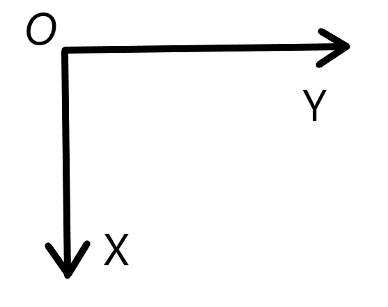
X轴与Y轴坐标轴
2.蓝牙读取和写入
#define RXBUF_SIZE 1024     // DMA buffer size
#define size(a)   (sizeof(a) / sizeof(*(a)))

/* Global Variable */
u8 TxBuffer[] = " ";
u8 RxBuffer[RXBUF_SIZE]={0};


/*******************************************************************************
* Function Name  : USARTx_CFG
* Description    : Initializes the USART peripheral.
* 描述    :   串口初始化
* Input          : None
* Return         : None
*******************************************************************************/
void USARTx_CFG(void)
{
    GPIO_InitTypeDef  GPIO_InitStructure;
    USART_InitTypeDef USART_InitStructure;
    //开启时钟
    RCC_APB1PeriphClockCmd(RCC_APB1Periph_UART7, ENABLE);
    RCC_APB2PeriphClockCmd(RCC_APB2Periph_GPIOC, ENABLE);

    /* USART7 TX-->C2  RX-->C3 */
    GPIO_InitStructure.GPIO_Pin = GPIO_Pin_2;
    GPIO_InitStructure.GPIO_Speed = GPIO_Speed_50MHz;
    GPIO_InitStructure.GPIO_Mode = GPIO_Mode_AF_PP;
    GPIO_Init(GPIOC, &GPIO_InitStructure);
    GPIO_InitStructure.GPIO_Pin = GPIO_Pin_3;
    GPIO_InitStructure.GPIO_Mode = GPIO_Mode_IPU;           //RX,输入上拉
    GPIO_Init(GPIOC, &GPIO_InitStructure);

    USART_InitStructure.USART_BaudRate = 115200;                    // 波特率
    USART_InitStructure.USART_WordLength = USART_WordLength_8b;     // 数据位 8
    USART_InitStructure.USART_StopBits = USART_StopBits_1;          // 停止位 1
    USART_InitStructure.USART_Parity = USART_Parity_No;             // 无校验
    USART_InitStructure.USART_HardwareFlowControl = USART_HardwareFlowControl_None; // 无硬件流控
    USART_InitStructure.USART_Mode = USART_Mode_Tx | USART_Mode_Rx; //使能 RX 和 TX

    USART_Init(UART7, &USART_InitStructure);
    DMA_Cmd(DMA2_Channel9, ENABLE);                                  //开启接收 DMA
    USART_Cmd(UART7, ENABLE);                                        //开启UART
}

/*******************************************************************************
* Function Name  : DMA_INIT
* Description    : Configures the DMA.
* 描述    :   DMA 初始化
* Input          : None
* Return         : None
*******************************************************************************/
void DMA_INIT(void)
{
    DMA_InitTypeDef DMA_InitStructure;
    RCC_AHBPeriphClockCmd(RCC_AHBPeriph_DMA2, ENABLE);

    // TX DMA 初始化
    DMA_DeInit(DMA2_Channel8);
    DMA_InitStructure.DMA_PeripheralBaseAddr = (u32)(&UART7->DATAR);        // DMA 外设基址,需指向对应的外设
    DMA_InitStructure.DMA_MemoryBaseAddr = (u32)TxBuffer;                   // DMA 内存基址,指向发送缓冲区的首地址
    DMA_InitStructure.DMA_DIR = DMA_DIR_PeripheralDST;                      // 方向 : 外设 作为 终点,即 内存 ->  外设
    DMA_InitStructure.DMA_BufferSize = 0;                                   // 缓冲区大小,即要DMA发送的数据长度,目前没有数据可发
    DMA_InitStructure.DMA_PeripheralInc = DMA_PeripheralInc_Disable;        // 外设地址自增,禁用
    DMA_InitStructure.DMA_MemoryInc = DMA_MemoryInc_Enable;                 // 内存地址自增,启用
    DMA_InitStructure.DMA_PeripheralDataSize = DMA_PeripheralDataSize_Byte; // 外设数据位宽,8位(Byte)
    DMA_InitStructure.DMA_MemoryDataSize = DMA_MemoryDataSize_Byte;         // 内存数据位宽,8位(Byte)
    DMA_InitStructure.DMA_Mode = DMA_Mode_Normal;                           // 普通模式,发完结束,不循环发送
    DMA_InitStructure.DMA_Priority = DMA_Priority_VeryHigh;                 // 优先级最高
    DMA_InitStructure.DMA_M2M = DMA_M2M_Disable;                            // M2P,禁用M2M
    DMA_Init(DMA2_Channel8, &DMA_InitStructure);

    // RX DMA 初始化,环形缓冲区自动接收
    DMA_DeInit(DMA2_Channel9);
    DMA_InitStructure.DMA_PeripheralBaseAddr = (u32)(&UART7->DATAR);
    DMA_InitStructure.DMA_MemoryBaseAddr = (u32)RxBuffer;                   // 接收缓冲区
    DMA_InitStructure.DMA_DIR = DMA_DIR_PeripheralSRC;                      // 方向 : 外设 作为 源,即 内存 <- 外设
    DMA_InitStructure.DMA_BufferSize = RXBUF_SIZE;                          // 缓冲区长度为 RXBUF_SIZE
    DMA_InitStructure.DMA_Mode = DMA_Mode_Circular;                         // 循环模式,构成环形缓冲区
    DMA_Init(DMA2_Channel9, &DMA_InitStructure);

}


/*******************************************************************************
* Function Name  : GPIO_CFG
* Description    : Initializes GPIOs.
* 描述    :   GPIO 初始化
* Input          : None
* Return         : None
*******************************************************************************/
void GPIO_CFG(void)
{
    GPIO_InitTypeDef  GPIO_InitStructure;
    // CH9141 配置引脚初始化
    RCC_APB2PeriphClockCmd(RCC_APB2Periph_GPIOA, ENABLE);
    RCC_APB2PeriphClockCmd(RCC_APB2Periph_GPIOC, ENABLE);
    /* BLE_sleep --> C13  BLE_AT-->A7 */
    GPIO_InitStructure.GPIO_Pin = GPIO_Pin_13;
    GPIO_InitStructure.GPIO_Speed = GPIO_Speed_50MHz;
    GPIO_InitStructure.GPIO_Mode = GPIO_Mode_Out_PP;
    GPIO_Init(GPIOC, &GPIO_InitStructure);
//    GPIO_InitStructure.GPIO_Pin = GPIO_Pin_7;
//    GPIO_InitStructure.GPIO_Mode = GPIO_Mode_Out_PP;
//    GPIO_Init(GPIOA, &GPIO_InitStructure);
}
/*******************************************************************************
* Function Name  :  uartWriteBLE
* Description    :  send data to BLE via UART7          向蓝牙模组发送数据
* Input          :  char * data          data to send   要发送的数据的首地址
*                   uint16_t num         number of data 数据长度
* Return         :  RESET                UART7 busy,failed to send  发送失败
*                   SET                  send success               发送成功
*******************************************************************************/
FlagStatus uartWriteBLE(char * data , uint16_t num)
{
    //如上次发送未完成,返回
    if(DMA_GetCurrDataCounter(DMA2_Channel8) != 0){
        return RESET;
    }

    DMA_ClearFlag(DMA2_FLAG_TC8);
    DMA_Cmd(DMA2_Channel8, DISABLE );           // 关 DMA 后操作
    DMA2_Channel8->MADDR = (uint32_t)data;      // 发送缓冲区为 data
    DMA_SetCurrDataCounter(DMA2_Channel8,num);  // 设置缓冲区长度
    DMA_Cmd(DMA2_Channel8, ENABLE);             // 开 DMA
    return SET;
}

/*******************************************************************************
* Function Name  :  uartWriteBLEstr
* Description    :  send string to BLE via UART7    向蓝牙模组发送字符串
* Input          :  char * str          string to send
* Return         :  RESET                UART7 busy,failed to send  发送失败
*                   SET                  send success               发送成功
*******************************************************************************/
FlagStatus uartWriteBLEstr(char * str)
{
    uint16_t num = 0;
    while(str[num])num++;           // 计算字符串长度
    return uartWriteBLE(str,num);
}


/*******************************************************************************
* Function Name  :  uartReadBLE
* Description    :  read some bytes from receive buffer 从接收缓冲区读出一组数据
* Input          :  char * buffer        buffer to storage the data 用来存放读出数据的地址
*                   uint16_t num         number of data to read     要读的字节数
* Return         :  int                  number of bytes read       返回实际读出的字节数
*******************************************************************************/
uint16_t rxBufferReadPos = 0;       //接收缓冲区读指针
uint32_t uartReadBLE(char * buffer , uint16_t num)
{
    uint16_t rxBufferEnd = RXBUF_SIZE - DMA_GetCurrDataCounter(DMA2_Channel9); //计算 DMA 数据尾的位置
    uint16_t i = 0;

    if (rxBufferReadPos == rxBufferEnd){
        // 无数据,返回
        return 0;
    }

    while (rxBufferReadPos!=rxBufferEnd && i < num){
        buffer[i] = RxBuffer[rxBufferReadPos];
        i++;
        rxBufferReadPos++;
        if(rxBufferReadPos >= RXBUF_SIZE){
            // 超出缓冲区,回零
            rxBufferReadPos = 0;
        }
    }
    return i;
}

/*******************************************************************************
* Function Name  :  uartReadByteBLE
* Description    :  read one byte from UART buffer  从接收缓冲区读出 1 字节数据
* Input          :  None
* Return         :  char    read data               返回读出的数据(无数据也返回0)
*******************************************************************************/
char uartReadByteBLE()
{
    char ret;
    uint16_t rxBufferEnd = RXBUF_SIZE - DMA_GetCurrDataCounter(DMA2_Channel9);//计算 DMA 数据尾的位置
    if (rxBufferReadPos == rxBufferEnd){
        // 无数据,返回
        return 0;
    }
    ret = RxBuffer[rxBufferReadPos];
    rxBufferReadPos++;
    if(rxBufferReadPos >= RXBUF_SIZE){
        // 超出缓冲区,回零
        rxBufferReadPos = 0;
    }
    return ret;
}
/*******************************************************************************
* Function Name  :  uartAvailableBLE
* Description    :  get number of bytes Available to read from the UART buffer  获取缓冲区中可读数据的数量
* Input          :  None
* Return         :  uint16_t    number of bytes Available to readd              返回可读数据数量
*******************************************************************************/
uint16_t uartAvailableBLE()
{
    uint16_t rxBufferEnd = RXBUF_SIZE - DMA_GetCurrDataCounter(DMA2_Channel9);//计算 DMA 数据尾的位置
    // 计算可读字节
    if (rxBufferReadPos <= rxBufferEnd){
        return rxBufferEnd - rxBufferReadPos;
    }else{
        return rxBufferEnd +RXBUF_SIZE -rxBufferReadPos;
    }
}
本次使用的蓝牙读取和写入的部分采用DMA搬运数据,使用的串口输出为UART1(库里面自带输出函数printf),注意跳线帽应保证与RX1和TX1相连,这样WCHLink串口才能接收到数据。
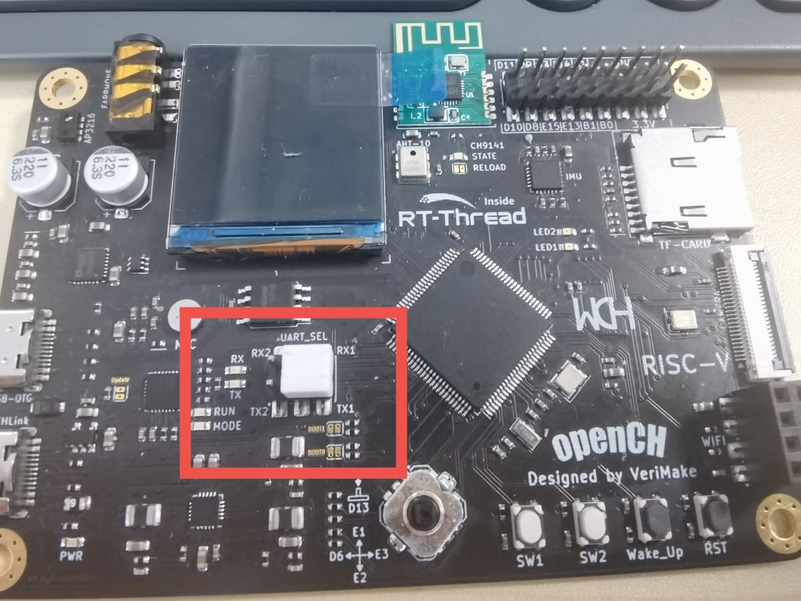
| 端口功能 | 引脚功能 | 功能 | 备注 |
|---|
| 串口1 | PA2 | UART1_TX | 复用:DVP_D0 |
| PA3 | UART1_RX | 复用:DVP_D1 |
| 蓝牙 CH9141 | PC2 | UART7_TX | CH9141_RX |
| PC3 | UART7_RX | CH9141_TX |
| PA7 | BLE_AT | BLE控制管脚 0为AT模式,1为透传模式 |
| PC13 | BLE_SLEEP | 低电平有效,低功耗模式 |
3.main函数
int main(void)
{
    NVIC_PriorityGroupConfig(NVIC_PriorityGroup_2);
    Delay_Init();
    USART_Printf_Init(115200);
    printf("SystemClk:%d\r\n",SystemCoreClock);

    DMA_INIT();
    USARTx_CFG();                                                 /* USART INIT */
    USART_DMACmd(UART7,USART_DMAReq_Tx|USART_DMAReq_Rx,ENABLE);

    lcd_init();
    lcd_set_color(BLACK,WHITE);
    lcd_show_string(50, 0, 32,"Yuimerlin");
    lcd_set_color(BLACK,RED);
    lcd_show_string(0, 32, 16,"BLE Device Test");
    delay_ms(100);

    GPIO_CFG();
//    GPIO_WriteBit(GPIOA, GPIO_Pin_7,RESET); //进入 AT
    GPIO_WriteBit(GPIOC, GPIO_Pin_13,SET); //enable CH9141
    Delay_Ms(1000);
    while(1){
        Delay_Ms(400);
        int num = uartAvailableBLE();             //读取蓝牙字符串
        if (num > 0 ){
            char buffer[1024]={"\0"};
            uartReadBLE(buffer , num);
            lcd_set_color(BLACK,GREEN);           //将读取的字符串显示在屏幕上
            lcd_show_string(30, 208, 16,"Receive    : %8s", buffer);
            printf("Revceived:%s\r\n",buffer);    //将收到的字符串发送给串口
        }
 //       GPIO_WriteBit(GPIOA, GPIO_Pin_7,SET); // 退出AT。可用手机或电脑连接CH9141,测试数据收发
    }

}
程序流程:
- 初始化各模块,屏幕上显示这次例程的作者和主题;
- 关闭蓝牙模块的低功耗模式,并读取蓝牙发送的数据;
- 将读取的数据显示与LCD屏幕,并将其发送给WCHLink串口。

首先在BLE虚拟串口管理器启动之前设定好的串口。
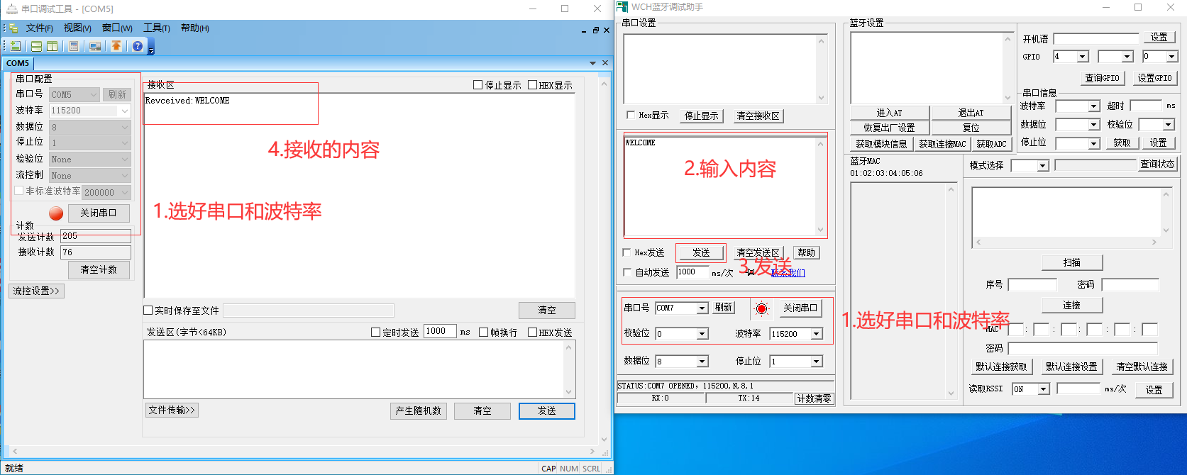
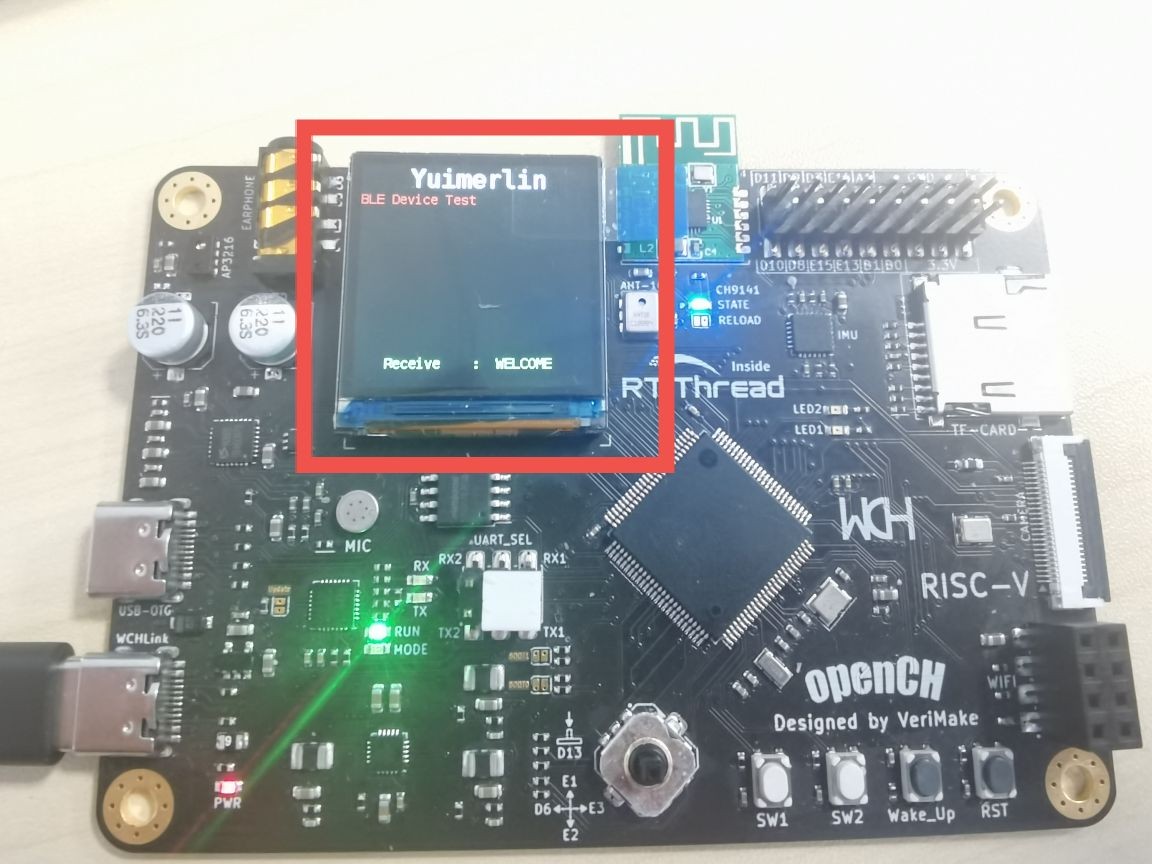
选好对应的串口和波特率,波特率设定为115200,将输入的内容发送出去,可以看到串口5(WCHLink)收到了发出的内容。也可以看到LCD屏幕上有了显示。成功完成了电脑对赤菟板的通信。
后话
这篇教程仅为CH32V307的蓝牙教程的上篇,为了防止混乱,这次仅演示电脑与板子连接的例程,手机端连接好了直接在对话模式下发送数据。我会尽快更新续篇的。
这次的程序和之前一样放到了gitee仓库上,文件名为:LCD_BLE
欢迎大家参考!
 网站备案号:ICP备16046599号-1